CS616 – Software Engineering II |
|
Lecture 2 |
Object-Oriented Design
Four layers of
the OO design pyramid:
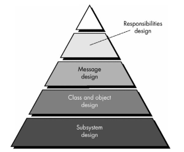
- Subsystem layer contains a representation of each of the subsystems that:
- enable the software to achieve its customer-defined requirements
- implement the technical infrastructure that supports customer requirements.
- Class and object layer contains:
- class hierarchies that enable system to be created using generalizations
- representations of each object.
- Message layer :
- contains the design details that enable each object to communicate with its collaborators
- establishes the external and internal interfaces for the system.
- Responsibilities layer contains the data structure and algorithmic design for all attributes and operations for each object.
· Hidden Underlying Layer -> Foundation layer:
o Focuses on the design of domain objects (called design patterns).
o Domain objects provide support for human/computer interface activities, task management, and data management.
o Domain objects can be used to flesh out the design of the application itself.
Conventional vs. OO Approaches
·
Conventional approaches: apply a distinct notation and
set of heuristics to map the analysis model into a design model.
· Each element of the conventional analysis model maps into one or more layers of the design model.
· OOD applies:
o data design when attributes are represented
o interface design when a messaging model is developed
o component-level (procedural) design for the design of operations.
· Architecture of an OO design has more to do with the collaborations among objects than with the flow of control between components of the system.
· Relationship between the OO analysis model and design model:
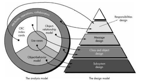
· Subsystem design is derived by:
o considering overall customer requirements (represented with use-cases)
o events and states that are externally observable (the object-behavior model)
· Class and object design :
o mapped from the description of attributes, operations, and collaborations contained in the CRC model.
· Message design driven by:
o the object-relationship model
o responsibilities design is derived using the attributes, operations, and collaborations described in the CRC model.
Design Issues
Five criteria for judging a design
method's ability to achieve modularity:
- Decomposability—the facility with which a design method helps the designer to decompose a large problem into subproblems that are easier to solve.
- Composability—the degree to which a design method ensures that program components (modules), once designed and built, can be reused to create other systems.
- Understandability—the ease with which a program component can be understood without reference to other information or other modules.
- Continuity—the ability to make small changes in a program and have these changes manifest themselves with corresponding changes in just one or a very few modules.
- Protection—an architectural characteristic that will reduce the propagation of side effects if an error does occur in a given module.
Five basic design principles that can be derived for
modular architectures:
(1)
linguistic modular units
·
programming language used should be capable of
supporting the modularity defined directly
(2)
few interfaces
·
to achieve low coupling - the number of interfaces
between modules should be minimized
(3)
small interfaces (weak coupling)
·
to achieve low coupling - the amount of information
that moves across an interface should be minimized
(4)
explicit interfaces
·
components should communicate in an obvious and direct
way
(5)
information hiding
·
all information about a component is hidden from
outside access
The OOD Landscape
Most important early OOD methods:
- The Booch method.
- encompasses both "micro development process" and "macro development process."
- design context
- macro development encompasses:
- architectural planning activity that:
- clusters similar objects in separate architectural partitions
- layers objects by level of abstraction
- identifies relevant scenarios
- creates a design prototype
- validates the design prototype by applying it to usage scenarios.
- micro development:
- defines a set of "rules" that govern:
- the use of operations and attributes and the domain-specific policies for memory management
- error handling and other infrastructure functions
- develops scenarios that describe the semantics of the rules and policies
- creates a prototype for each policy
- instruments and refines the prototype
- reviews each policy so that it "broadcasts its architectural vision"
- The Rumbaugh method.
- encompasses a design activity that encourages design to be conducted at two different levels of abstraction:
- System design -
- focuses on the layout of components that are needed to construct a complete product or system
- analysis model is partitioned into subsystems -> allocated to processors and tasks.
- strategy for implementing data management is defined
- global resources and the control mechanisms required to access them are identified
- Object design –
- emphasizes the detailed layout of an individual object.
- operations are selected from the analysis model and algorithms are defined for each operation.
- data structures appropriate to attributes and algorithms are represented.
- classes and class attributes are designed so they optimize data access and improve computational efficiency.
- a messaging model is created to implement the object relationships (associations).
- The Jacobson method.
- design model emphasizes traceability to the OOSE analysis model
1. idealized analysis model is adapted to fit the real world environment.
2. primary design objects, called blocks are created and categorized as interface blocks, entity blocks, and control blocks
3. communication between blocks during execution is defined
4. blocks are organized into subsystems.
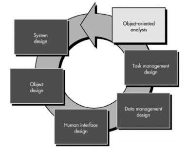
- The Coad and Yourdon method.
- design approach addresses not only the application but also the infrastructure for the application
- focuses on the representation of four major system components:
1. problem domain component
2. human interaction component
3. task management component
4. data management component.
To perform object-oriented
design, a software engineer should perform the following generic steps:
- Describe each subsystem and allocate it to processors and tasks.
- Choose a design strategy for implementing data management, interface support, and task management.
- Design an appropriate control mechanism for the system.
- Perform object design by creating a procedural representation for each operation and data structures for class attributes.
- Perform message design using collaborations between objects and object relationships.
- Create the messaging model.
- Review the design model and iterate as required.
Note: design steps are iterative.
Unified Approach to OOD
Unified Modeling Language (UML)
§ During analysis modeling the user model and structural model views are represented
o provide insight into the usage scenarios for the system (providing guidance for behavioral modeling
o establish a foundation for the implementation and environment model views by identifying and describing the static structural elements of the system.
§ UML is organized into two major design activities:
o system
design:
§ Primary objective of UML system design is to represent the software architecture
· conceptual architecture is concerned with the structure of the static class model and the connections between components of the model
· module architecture describes the way the system is divided into subsystems or modules and how they communicate by exporting and importing data
· code architecture defines how the program code is organized into files and directories and grouped into libraries.
· execution architecture focuses on the dynamic aspects of the system and the communication between components as tasks and operations execute.
o object design
o UML object design focuses on a description of objects and their interactions with one another.
o detailed specification of attribute data structures and a procedural design of all operations are created.
o visibility for all class attributes is defined and interfaces between objects are elaborated to define the details of a complete messaging model
§ System and object design are extended to consider:
o design of user interfaces
§ user model view drives the user interface design process
§ provides a scenario that is elaborated iteratively to become a set of interface classes
o data management with the system to be built
§ establishes a set of classes and collaborations that allow the system (product) to manage persistent data (e.g., files and databases)
o task management for the subsystems that have been specified.
§ establishes the infrastructure that organizes subsystems into tasks and then manages task concurrency.
§ Process flow for OOD
The System Design Process
§ System design develops the architectural detail required to build a system or product.
§ System design encompasses the following activities:
1. Partition the analysis model into subsystems.
2. Identify concurrency that is dictated by the problem.
3. Allocate subsystems to processors and tasks.
4. Develop a design for the user interface.
5. Choose a basic strategy for implementing data management.
6. Identify global resources and the control mechanisms required to access them.
7. Design an appropriate control mechanism for the system, including task management.
8. Consider how boundary conditions should be handled.
9. Review and consider trade-offs.
1. Partition the Analysis Model
§ Partition the analysis model to define cohesive collections of classes, relationships, and behavior -> subsytems
§ These design elements are packaged as a subsystem.
§ all of the elements of a subsystem share some property in common
§ all may be involved in accomplishing the same function
§ they may reside within the same product hardware, or they may manage the same class of resources
§ Subsystems are characterized by their responsibilities -> identified by the services that they provide
§ a service is a collection of operations that perform a specific function (e.g., managing word-processor files, producing a three-dimensional rendering, translating an analog video signal into a compressed digital image)
§ Subsystems should conform to the following design criteria:
§ Subsystem should have a well-defined interface through which all communication with the rest of the system occurs.
§ classes within a subsystem should collaborate only with other classes within the subsystem.
§ The number of subsystems should be kept low.
§ A subsystem can be partitioned internally to help reduce complexity.
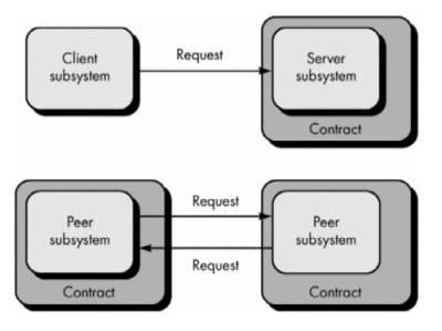
§ When two subsystems communicate with one another, they can establish a client/server link or a peer-to-peer link
§ client/server link –
1. each subsystem takes on one of the roles implied by client and server.
2. service flows from server to client in only one direction.
§ peer-to-peer link –
3. services may flow in either direction.
§ layering occurs when a system is partitioned into subsystems.
§ each layer of an OO system contains one or more subsystems and represents a different level of abstraction of the functionality required to accomplish system functions.
§ levels of abstraction are determined by the degree to which the processing associated with a subsystem is visible to an end-user.
§ e.g. four-layer architecture might might include
(1) presentation layer (the subsystems associated with the user interface)
(2) application layer (the subsystems that perform the processing associated with the application)
(3) data formatting layer (the subsystems that prepare the data for processing)
(4) database layer (the subsystems associated with data management).
§ Each layer moves deeper into the system, representing increasingly more environment-specific processing.
· Design approach for layering:
1. Establish layering criteria. That is, decide how subsystems will be grouped in a layered architecture.
2. Determine the number of layers. Too many introduce unnecessary complexity; too few may harm functional independence.
3. Name the layers and allocate subsystems (with their encapsulated classes) to a layer. Be certain that communication between subsystems (classes) on one layer and other subsystems (classes) at another layer follow the design philosophy for the architecture
4. Design interfaces for each layer.
5. Refine the subsystems to establish the class structure for each layer.
6. Define the messaging model for communication between layers.
7. Review the layer design to ensure that coupling between layers is minimized (a client/server protocol can help accomplish this).
8. Iterate to refine the layered design.
2 Concurrency and Subsystem Allocation
· Dynamic aspect of the object-behavior model provides an indication of concurrency among classes (or subsystems)
· If classes (or subsystems) are not active at the same time:
§ no need for concurrent processing
§ classes (or subsystems) can be implemented on the same processor hardware.
· If classes (or subsystems) must act on events asynchronously and at the same time, they are viewed as concurrent.
· When subsystems are concurrent, two allocation options exist:
1. allocate each subsystem to an independent processor
2. allocate the subsystems to the same processor and provide concurrency support through operating system features.
· Concurrent tasks are defined by examining the state diagram for each object
§ If the flow of events and transitions indicates that only a single object is active at any one time a thread of control has been established.
§ The thread of control continues even when one object sends a message to another object, as long as the first object waits for a response.
§ If the first object continues processing after sending a message, the thread of control splits.
§ Tasks in an OO system are designed by isolating threads of control
§ e.g. while the SafeHome security system is monitoring its sensors, it can also be dialing the central monitoring station for verification of connection.
· Since the objects involved in both of these behaviors are active at the same time, each represents a separate thread of control and each can be defined as a separate task.
· If the monitoring and dialing activities occur sequentially, a single task could be implemented.
· To determine which of the processor allocation options is appropriate, the designer must consider performance requirements, costs, and the overhead imposed by interprocessor communication.
3 The Task Management Component
· Strategy for the design of the objects that manage concurrent tasks:
o The characteristics of the task are determined
§ by understanding how the task is initiated
§ Event-driven and clock-driven tasks are most common
§ Both activated by an interrupts
o A coordinator task and associated objects are defined.
o The coordinator and other tasks are integrated.
· Priority and criticality of the task must also be determined.
o High-priority tasks must have immediate access to system resources.
o High-criticality tasks must continue to operate even if resource availability is reduced or the system is operating in a degraded state.
· Once the characteristics of the task have been determined, object attributes and operations required to achieve coordination and communication with other tasks are defined.
The basic task template (for a task object) takes the form
Task name—the name of the object
Description—a narrative describing the purpose of the object
Priority—task priority (e.g., low, medium, high)
Services—a list of operations that are responsibilities of the object
Coordinates by—the manner in which object behavior is invoked
Communicates via—input and output data values relevant to the task
4 The User Interface Component
· The user interface represents a critically important subsystem for most modern applications.
· OO analysis model contains:
o usage scenarios (called use-cases)
o descriptions of the roles that users play (called actors) as they interact with the system.
o These serve as input to the user interface design process.
· Once the actor and its usage scenario are defined, a command hierarchy is identified.
1. The command hierarchy defines major system menu categories (the menu bar or tool palette) and all subfunctions that are available within the context of a major system menu category (the menu windows).
2. The command hierarchy is refined iteratively until every use-case can be implemented by navigating the hierarchy of functions.
· Because a wide variety of user interface development environments already exist, the design of GUI elements is not necessary
5 The Data Management Component
· Data management encompasses two distinct areas of concern:
· the management of data that are critical to the application itself
· the creation of an infrastructure for storage and retrieval of objects.
· Data management is designed in a layered fashion
§ isolate the low-level requirements for manipulating data structures from the higher-level requirements for handling system attributes.
· A Database management system is often used as a common data store for all subsystems
§ The objects required to manipulate the database are:
(1) members of reusable classes that are identified using domain analysis
(2) supplied directly by the database vendor
· The design of the data management component includes the design of the attributes and operations required to manage objects.
6 The Resource Management Component
· Different resources are available to an OO system or product
· Subsystems compete for these resources at the same time.
· Global system resources can be external entities (e.g., a disk drive, processor, or communication line) or abstractions (e.g., a database, an object).
· Regardless of the nature of the resource - design a control mechanism for it.
7 Intersubsystem Communication
· Once each subsystem has been specified define the collaborations that exist between the subsystems
· The model that we use for object-to-object collaboration can be extended to subsystems as a whole.
· A collaboration model:
· Communication can occur by establishing a client/server link or a peer-to-peer link.
· Must specify the contract that exists between subsystems.
· A contract provides an indication of the ways in which one subsystem can interact with another.
· The following design steps can be applied to specify a contract for a subsystem
- List each request that can be made by collaborators of the subsystem.
· Organize the requests by subsystem and define them within one or more appropriate contracts. Be sure to note contracts that are inherited from superclasses.
- For each contract, note the operations (both inherited and private) that are required to implement the responsibilities implied by the contract.
· Associate the operations with specific classes that reside within a subsystem.
- Considering one contract at a time, create a table of the form shown in below.
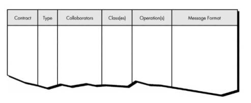
· For each contract, the following entries are made in the table:
Type—the type of contract (i.e., client/server or peer-to-peer).
Collaborators—the names of the subsystems that are parties to the contract.
Class—the names of the classes (contained within a subsystem) that support services implied by the contract.
Operation—the names of the operations (within the class) that implement the services.
Message format—the message format required to implement the interaction between collaborators.
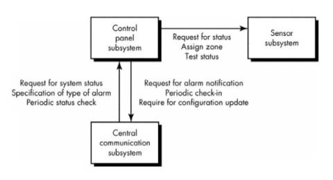
· Draft an appropriate message description for each interaction between the subsystems.
- If the modes of interaction between subsystems are complex, a subsystem-collaboration diagram is created.
· Each subsystem is represented along with its interactions with other subsystems.
1. contracts that are invoked during an interaction are noted as shown.
2. details of the interaction are determined by looking up the contract in the subsystem collaboration table
The Object Design Process
· Object design is concerned with the detailed design of the objects and their interactions.
· It is completed within the overall architecture defined during system design and according to agreed design guidelines and protocols.
·
Object design is particularly concerned with the
specification of attribute types, how operations function, and how objects are
linked to other objects.
Object Descriptions
· A design description of an object (an instance of a class or subclass) can take one of two forms:
1. a protocol description that establishes the interface of an object by defining each message that the object can receive and the related operation that the object performs when it receives the message
2. an implementation description that shows implementation details for each operation implied by a message that is passed to an object. Implementation details include information about the object's private part; that is, internal details about the data structures that describe the object's attributes and procedural details that describe operations.
· Protocol description is a set of messages and a corresponding comment for each message.
· e.g. a portion of the protocol description for the object motion sensor to read the sensor
![]()
· Implementation
description of an object provides the internal ("hidden") details
that are required for implementation but are not necessary for invocation.
o
Composed of the following information:
(1) a specification of the object's name and reference to class
(2)
a specification of private data structure with indication of
data items and types
(3)
a procedural description of each operation or pointers to such
procedural descriptions.
o
Must contain sufficient information to provide for
proper handling of all messages described in the protocol description.
Designing Algorithms and Data Structures
· Representations contained in the analysis model and the system design provide a specification for all operations and attributes.
· Algorithms and data structures are designed using an approach that differs little from the data design and component-level design approaches discussed for conventional software engineering.
· An
algorithm is created to implement the specification for each operation.
· Data structures are designed concurrently with algorithms.
· Operations manipulate the attributes of a class
o
Three broad categories:
1. operations that manipulate data in some way (e.g., adding, deleting, reformatting, selecting)
2.
operations that perform a computation
3.
operations that monitor an object for the occurrence of a
controlling event.
· e.g., SafeHome processing narrative contains the sentence fragments:
"sensor is assigned a number and type"
"a master password is programmed for arming and disarming the system."
· These two phrases indicate:
· That an assign operation is relevant for the sensor object.
· That a program operation will be applied to the system object.
·
That arm and disarm are operations that
apply to system (also that system status
may ultimately be defined (using data dictionary notation) as
system status = [armed | disarmed]
· The
operation program is allocated during OOA, but during object design it
will be refined into a number of more specific operations required to configure
the system.
o
e.g., after discussions with product engineering, the
analyst, and the marketing department, the designer might elaborate the
original processing narrative and write the following for program (potential
operations—verbs—are underlined):
Program enables the SafeHome user to configure the
system once it has been installed. The user can (1) install phone
numbers; (2) define delay times for alarms; (3) build a sensor
table that contains each sensor ID, its type, and location; and (4) load
a master password.
o The
single operation program and replaced it with the operations: install,
define, build, and load.
o Each of these new operations:
§ becomes part of the system object
§ has knowledge of the internal data structures that implement the object's attributes
§ is invoked by sending the object messages of the form
MESSAGE (system) --> install: SENDS telephone.number;
§
an emergency phone number is given by an install
message will be sent to system.
· Verbs connote actions or occurrences
o For object design consider verbs and descriptive verb phrases and predicates (e.g., "is equal to") as potential operations.
o
Grammatical parse is applied recursively until each
operation has been refined to its most-detailed level.
· After basic object model is created optimization occurs
o Three major thrusts for OOD design optimization:
§ Review the object-relationship model to ensure that the implemented design leads to efficient utilization of resources and ease of implementation. Add redundancy where necessary.
§ Revise
attribute data structures and corresponding operation algorithms to enhance
efficient processing.
§
Create new attributes to save derived information,
thereby avoiding recomputation.
Program Components and Interfaces
· An important aspect of software design quality is modularity;
· Object-oriented approach defines the object as a program component that is linked to other components (e.g., private data, operations).
· During
design identify the interfaces between objects and the overall structure of the
objects.
· A program component is a design abstraction
o should be represented in the context of the programming language used for implementation
o For OOD, the programming language should be capable of creating the following program component (modeled after Ada):
· Program component is specified by indicating both data objects and operations
o specification part of the component indicates all data objects (declared with the TYPE statement) and the operations (PROC for procedure) that act on them
o
private part (PRIVATE) of the component gives hidden details of
data structure and processing.
· First program component to be identified should be the highest-level module from which all processing originates and all data structures evolve.
o e.g. SafeHome, we can define the highest-level program component as
PROCEDURE SafeHome software
o SafeHome software component can be coupled with a preliminary design for the following packages (objects):
· Data objects and corresponding operations are specified for each of the program components for SafeHome software
· Final
step in design process: complete all information required to fully implement
data structure and types contained in the PRIVATE portion of the package and all procedural
detail contained in the PACKAGE
BODY.
o e.g. sensor package
§ data structures for sensor attributes have already been defined
§ first step is to define the interfaces for each of the operations attached to sensor:
PROC read (sensor.id, sensor.status:
OUT);
PROC set (alarm.characteristics,
hardware.interface: IN)
PROC test (sensor.id, sensor.status, alarm.characteristics: OUT);
· next
step -> stepwise refinement of each operation associated with the sensor package
o
e.g. develop a processing narrative (an informal
strategy) for read:
When the sensor object receives a read message, the read process is invoked. The process determines the interface and signal type, polls the sensor interface, converts A/D characteristics into an internal signal level, and compares the internal signal level to a threshold value. If the threshold is exceeded, the sensor status is set to "event." Otherwise, the sensor status is set to "no event." If an error is sensed while polling the sensor, the sensor status is set to "error."
o description of the read process can be developed:
o translate into the appropriate implementation language
Design Patterns
· Recurring patterns of classes and communicating objects exist in many object-oriented systems
· These patterns solve specific design problems and make object-oriented design more flexible, elegant, and ultimately reusable
· Help designers reuse successful designs by basing new designs on prior experience
· A designer who is familiar with such patterns can apply them immediately to design problems without having to rediscover them.
Describing a Design Pattern
· All design patterns can be described by specifying the following information
- the name of the pattern
- the intent of the pattern
- the "design forces" that motivate the pattern
- the solution that mitigates these forces
- the classes that are required to implement the solution
- the responsibilities and collaboration among solution classes
- guidance that leads to effective implementation
- example source code or source code templates
- cross-references to related design patterns
· Design pattern name conveys significant meaning once the applicability and intent are understood
· Design forces:
o describe the data, functional, or behavioral requirements associated with part of the software for which the pattern is to be applied
o define the constraints that may restrict the manner in which the design is to be derived
· Pattern characteristics (classes, responsibilities, and collaborations) indicate the attributes of the design that may be adjusted to enable the pattern to accommodate a variety of problems
· Guidance associated with the use of a design pattern provides an indication of the ramifications of design decisions.
Using Patterns in Design
· Design patterns can be used by applying two different mechanisms:
o Inheritance
An existing design pattern becomes a template for a new subclass.
o Composition
Composition leads to aggregate objects
· A complex object can be assembled by selecting a set of design patterns and composing the appropriate object (or subsystem).
· Each design pattern is treated as a black box, and communication among the patterns occurs only via well-defined interfaces.
· Object composition should be favored over inheritance when both options exist
o Rather than creating large and unmanageable class hierarchies, composition favors small class hierarchies and objects that remain focused on one objective.
Object-Oriented Programming
- Software engineering viewpoint stresses OOA and OOD and considers OOP (coding) an important secondary activity that is an outgrowth of analysis and design
- As the complexity of systems increases, the design architecture of the end product has a significantly stronger influence on its success than the programming language that has been used
Object-Oriented Testing
· Construction of object-oriented software begins with the creation of analysis and design models
· These models begin as relatively informal representations of system requirements and evolve into detailed models of classes, class connections and relationships, system design and allocation, and object design (incorporating a model of object connectivity via messaging)
· Models can be tested at each stage to uncover errors prior to their propagation to the next iteration.
Testing OOA and OOD Models
Correctness of OOA and OOD Models
· Notation and syntax used to represent analysis and design models tied to the specific analysis and design method chosen for the project.
· Syntactic correctness is judged on proper use of the symbology
· Each model is reviewed to ensure that proper modeling conventions have been maintained.
· During analysis and design, semantic correctness must be judged based on the model's conformance to the real world problem domain.
· If the model accurately reflects the real world (to a level of detail that is appropriate to the stage of development at which the model is reviewed), then it is semantically correct.
· To determine whether the model does reflect the real world, it should be presented to problem domain experts, who will examine the class definitions and hierarchy for omissions and ambiguity
Consistency of OOA and OOD Models
· Consistency
of OOA and OOD models judged by "considering the relationships among
entities in the model
· To assess consistency, each class and its connections to other classes should be examined.
· One Approach: Use CRC and object-relationship model
To evaluate the class model use the following steps:
- Revisit the CRC model and the object-relationship model. Cross check to ensure that all collaborations implied by the OOA model are properly represented.
- Inspect the description of each CRC index card to determine if a delegated responsibility is part of the collaborator's definition.
- Invert the connection to ensure that each collaborator that is asked for service is receiving requests from a reasonable source.
- Using the inverted connections determine whether other classes might be required and whether responsibilities are properly grouped among the classes.
- Determine whether widely requested responsibilities might be combined into a single responsibility.
- Steps 1 through 5 are applied iteratively to each class and through each evolution of the OOA model.
· Reviews of the system design and the object design should also be conducted once the OOD model is created.
o The system design depicts:
§ the overall product architecture
§ the subsystems that compose the product
§ the manner in which subsystems are allocated to processors
§ the allocation of classes to subsystems
§ the design of the user interface.
o The object model presents:
§ the details of each class
§ the messaging activities that are necessary to implement collaborations between classes
· The system design is reviewed by examining the object-behavior model developed during OOA and mapping required system behavior against the subsystems designed to accomplish this behavior.
· Concurrency
and task allocation are reviewed within the context of system behavior.
o
The behavioral states of the system are evaluated to
determine which exist concurrently.
· Use-case
scenarios are used to exercise the user interface design.
· The object model is tested against the object-relationship network to ensure that all design objects contain the necessary attributes and operations to implement the collaborations defined for each CRC index card.
· The detailed specification of operation details (i.e., the algorithms that implement the operations) are reviewed using conventional inspection techniques.
Object-Oriented Testing Strategies
· Classical strategy for testing computer software: begin with "testing in the small" and work outward toward "testing in the large."
Unit Testing in the OO Context
· Encapsulation drives the definition of classes and objects
o
Each class and each instance of a class (object)
packages attributes (data) and the operations (also known as methods or services)
that manipulate these data.
· The
smallest testable unit is the encapsulated class or object
· Class testing for OO software is the equivalent of unit testing for conventional software
· Unlike unit testing of conventional software class testing for OO software is driven by the operations encapsulated by the class and the state behavior of the class
Integration Testing in the OO Context
Two different strategies for integration testing of OO systems:
1. thread-based testing - integrates the set of classes required to respond to one input or event for the system
· Each thread is integrated and tested individually.
· Regression testing is applied to ensure that no side effects occur.
2. use-based testing - tests those classes (independent classes) that use very few of server classes.
· After testing independent classes the next layer of classes, dependent classes, that use the independent classes are tested.
· Sequence of testing layers of dependent classes continues until the entire system is constructed
Cluster testing is one step in the integration testing of OO softwar
· A cluster of collaborating classes
· is exercised by designing test cases that attempt to uncover errors in the collaborations.
Validation Testing in an OO Context
· Validation of OO software focuses on user-visible actions and user-recognizable output from the system
· The tester should draw upon the use-cases that are part of the analysis model
· Use-case provides a scenario that has a high likelihood of uncovered errors in user interaction requirements.
· Conventional black-box testing methods can be used to drive validations tests
· Test cases may be derived from the object-behavior model and from event flow diagram created as part of OOA
Test Case Design for OO Software
· Overall approach to OO test case design:
- Each test case should be uniquely identified and explicitly associated with the class to be tested.
- The purpose of the test should be stated.
- A list of testing steps should be developed for each test and should contain [BER93]:
- A list of specified states for the object that is to be tested.
- A list of messages and operations that will be exercised as a consequence of the test.
- A list of exceptions that may occur as the object is tested.
- A list of external conditions (i.e., changes in the environment external to the software that must exist in order to properly conduct the test).
- Supplementary
information that will aid in understanding or implementing the test.
· Object-oriented testing focuses on designing appropriate sequences of operations to exercise the states of a class.
The Test Case Design Implications of OO Concepts
· OO class is the target for test case design
· Encapsulation makes testing operations outside of the class unproductive
· Unless built-in operations are provided to report the values for class attributes, a snapshot of the state of an object may be difficult to acquire.
· Inheritance leads to challenges
· Each new context of usage requires retesting, even though reuse has been achieved.
· Multiple inheritance complicates testing by increasing the number of contexts for which testing is required
o If subclasses instantiated from a superclass are used within the same problem domain, the set of test cases derived for the superclass can be used when testing the subclass.
o If the subclass is used in an entirely different context, the superclass test cases will have little applicability and a new set of tests must be designed.
Applicability of Conventional Test Case Design Methods
· White-box testing methods can be applied to the operations defined for a class
o Basis path, loop testing, or data flow techniques can help to ensure that every statement in an operation has been tested.
· Black-box testing methods are as appropriate for OO systems as they are for systems developed using conventional software engineering methods
o Use-cases can provide useful input in the design of black-box and state-based tests.
Fault-Based Testing
· The object of fault-based testing is to design tests that have a high likelihood of uncovering plausible faults
· Test cases are designed to exercise the design or code
· Errors occur at the boundaries of a problem.
o e.g., testing a SQRT operation that returns errors for negative numbers
§ try the boundaries: a negative number close to zero and zero itself.
§ "Zero itself" checks whether the programmer made a mistake like
if (x > 0) calculate_the_square_root();
instead of the correct
if (x >= 0) calculate_the_square_root();
o e.g., a Boolean expression:
if (a && !b | | c)
o Multicondition testing and related techniques probe for certain plausible faults in this expression, such as
&& should be | |
! was left out where it was needed
There should be parentheses around !b | | c
§ For each plausible fault design test cases that will force the incorrect expression to fail.
§ (a=0, b=0, c=0) will make
the expression as given evaluate false.
§ If the && should have been | |, the code has done the wrong thing and might branch to the wrong path.
· Integration testing looks for plausible faults in operation calls or message connections
· Three types of faults are encountered:
o unexpected result
o wrong operation/message used
o incorrect invocation
· To determine plausible faults as functions (operations) are invoked, the behavior of the operation must be examined.
· Integration
testing applies to attributes too.
· Object
"behaviors" are defined by the values that its attributes are
assigned.
· Testing should exercise the attributes to determine whether proper values occur for distinct types of object behavior.
The Impact of OO Programming on Testing
·
Object-oriented programming’s impact on testing
- Some types of faults become less plausible (not worth testing for).
- Some types of faults become more plausible (worth testing now).
- Some new types of faults appear.
· When an operation is invoked, it may be hard to tell exactly what code gets exercised.
o the operation may belong to one of many classes.
· Hard to determine the exact type or class of a parameter
o e.g. function call:
x = func (y);
o Must
consider the behaviors of base::func(),
of derived::func(), etc.
o Each
time func is
invoked, the tester must consider the union of all distinct behaviors.
Scenario-Based Test Design
· Fault-based testing misses two main types of errors:
1. incorrect specifications
2.
interactions among subsystems.
· Scenario-based testing concentrates on what the user does, not what the product does.
· It captures the tasks (via use-cases) that the user has to perform, then applys them and their variants as tests.
· Scenarios uncover interaction errors
· Scenario-based
testing exercises multiple subsystems in a single test.
· e.g.
the design of scenario-based tests for a text editor.
Use-Case: Fix the Final Draft
Background: It's not unusual to print the
"final" draft, read it, and discover some annoying errors that
weren't obvious from the on-screen image. This use-case describes the sequence of
events that occurs when this happens.
1.
Print the
entire document.
2.
Move around in
the document, changing certain pages.
3.
As each page is
changed, it's printed.
4.
Sometimes a
series of pages is printed.
·
Scenario describes two things: a test and specific user
needs.
·
The user needs:
(1) a method for printing single pages
(2)
a method for
printing a range of pages.
· There
is a need to test editing after printing (as well as the reverse).
· Tester
hopes to discover that the printing function causes errors in the editing
function.
Use-Case: Print a New Copy
Background: Someone asks the user for a fresh copy of the
document. It must be printed.
1. Open the document.
2. Print it.
3. Close the document.
· Document
was created in an earlier task. Does that task affect this one?
· Modern
editors - documents remember how they were last printed.
· After
the Fix the Final Draft scenario, just selecting "Print" in
the menu and clicking the "Print" button in the dialog box will cause
the last corrected page to print again.
· According
to the editor, the correct scenario should look like this:
Use-Case: Print a New Copy
1. Open the document.
2. Select "Print" in the menu.
3. Check if you're printing a page range; if so,
click to print the entire document.
4. Click on the Print button.
5. Close the document.
· This scenario indicates a potential specification error
· The editor does not do what the user reasonably expects it to do.
· Customers
will often overlook the check noted in step 3.
· They
will then be annoyed when they trot off to the printer and find one page when
they wanted 100. Annoyed customers signal specification bugs.
Testing Surface Structure and Deep Structure
· Surface structure refers to the externally observable structure of an OO program.
o
Capturing tasks involves understanding, watching, and
talking with users.
· Deep
structure refers to the internal technical details of an OO program.
o
Deep structure testing is designed to exercise
dependencies, behaviors, and communication mechanisms that have been
established as part of the system and object design of OO software.
o Analysis and design models are used as the basis for deep structure testing.
o Design representations of class hierarchy provide insight into inheritance structure.
Testing Methods Applicable at the Class Level
· Testing in the small focuses on a single class and the methods that are encapsulated by the class
· Random testing and partitioning are methods that can be used to exercise a class during OO testing
Random Testing for OO Classes
· e.g. consider a banking application in which an account class has the following operations: open, setup, deposit, withdraw, balance, summarize, creditLimit, and close.
o Each operation may be applied for account
o Certain constraints (e.g., the account must be opened before other operations can be applied and closed after all operations are completed) are implied by the nature of the problem.
o Even with these constraints, there are many permutations of the operations.
· Minimum
behavioral life history of an instance of account includes the following
operations:
open•setup•deposit•withdraw•close
· Represents the minimum test sequence for account.
· Other
behaviors may occur within this sequence:
open•setup•deposit•[deposit|withdraw|balance|summarize|creditLimit]n•withdraw•close
· A variety of different operation sequences can be generated randomly.
· For
example:
![]()
· These
and other random order tests are conducted to exercise different class instance
life histories.
Partition Testing at the Class Level
· Partition testing reduces the number of test cases required to exercise the class in much the same manner as equivalence partitioning.
· Partition
testing breaks down the input domain of a program into classes of data from
which test cases can be derived.
· Input
and output are categorized and test cases are designed to exercise each
category.
· State-based partitioning categorizes class operations based on their ability to change the state of the class.
o e.g. consider the account class:
· state operations include deposit and withdra
· nonstate operations include balance, summarize, and creditLimit
·
Tests are designed in a way that exercises operations
that change state and those that do not change state separately. ![]()
· Test case p1 changes state
·
Test case p2
exercises operations that do not change state
· Attribute-based
partitioning categorizes class operations based on the attributes that they
use.
o
For the account class:
·
attributes
balance and creditLimit can be used
to define partitions.
o
Operations are divided into three partitions:
1.
operations that use creditLimit
2.
operations that modify creditLimit
3.
operations that do not use or modify creditLimit.
o
Test sequences are then designed for each
partition.
· Category-based partitioning categorizes class operations based on the generic function that each performs.
· For example, operations in the account class can be categorized in:
o initialization operations (open, setup)
o computational operations (deposit, withdraw)
o queries (balance, summarize, creditLimit)
o
termination operations (close)
Interclass Test Case Design
· Test case design becomes more complicated as integration of the OO system begins.
· Testing of collaborations between classes must begin here.
· e.g. "interclass test case generation" - banking example includes classes and collaborations.
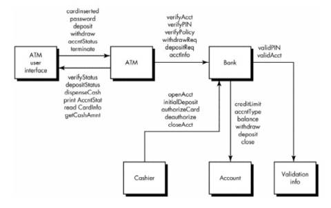
Class collaboration diagram for banking application
· Arrow direction in above indicates the direction of messages
· Labeling
indicates the operations that are invoked as a consequence of the
collaborations implied by the messages.
· Class collaboration testing can be accomplished by applying:
o random and partitioning methods
o scenario-based testing
o behavioral testing
Multiple Class Testing
· Sequence
of steps to generate multiple class random test cases:
- For each client class,
use the list of class operations to generate a series of random test
sequences. The operations will send messages to other server classes.
- For each message that is
generated, determine the collaborator class and the corresponding
operation in the server object.
- For each operation in the
server object (that has been invoked by messages sent from the client
object), determine the messages that it transmits.
- For each of the messages,
determine the next level of operations that are invoked and incorporate
these into the test sequence.
· e.g.
consider a sequence of operations for the bank class relative to an ATM
class:
verifyAcct•verifyPIN•[[verifyPolicy•withdrawReq]|depositReq|acctInfoREQ]n
o
A random test case for the bank class might be
![]()
o To test collaboration the messages associated with each of the operations noted in test case r3 are considered.
· Bank must collaborate with ValidationInfo to execute the verifyAcct and verifyPIN.
· Bank must collaborate with account to execute depositReq.
o
Hence,
a new test case that exercises these collaborations is
![]()
· Multiple class partition testing is similar to partition testing of individual classes
o A single class is partitioned
o The test sequence is expanded to include those operations that are invoked via messages to collaborating classes.
· Alternative approach partitions tests based on the interfaces to a particular class.
o The bank class receives messages from the ATM and cashier classes.
o The
methods within bank can therefore be tested by partitioning them into
those that serve ATM and those that serve cashier.
o
State-based partitioning can be used to refine the
partitions further.
Tests Derived from Behavior Models
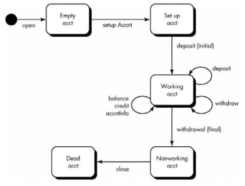
· State transition diagrams represent the dynamic behavior of a class.
· STD for a class can be used to help derive a sequence of tests that will exercise the dynamic behavior of the class (and those classes that collaborate with it).
· Above STD for the account class
o Initial transitions move through the empty acct and setup acct states.
o Majority of all behavior for instances of the class occurs while in the working acct state.
o
A final
withdrawal and close cause the account class to make transitions to the nonworking
acct and dead acct states
· Tests
should achieve all state coverage.
![]()
· This
sequence is the minimum test sequence. Adding additional test sequences to the
minimum sequence
![]()
· When
class behavior results in a collaboration with one or more classes, multiple
STDs are used to track the behavioral flow of the system.