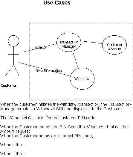
Use Cases are used at the beginning of a project (or cycle of a project) to capture user requirements for a system and give an initial idea of the system components that will directly interact with users. A Use Case shows one single "use" of a system by an external entity, either a person or another system. The external entity is called an "actor". Use cases both diagram and detail the usage of the system by the actor, showing which system components (classes) must participate in the use, and the sequence of user actions and system responses. Actors are drawn as stick figures outside the system boundary.
The accompanying explanation is a sequence of statements of the form "When....., then...."

Note that the description may preceed the diagram which will be derived from the descriptions. The use cases can later be used as the basis of a walk through the design to assure validity. They can also be used to validate the completed system.
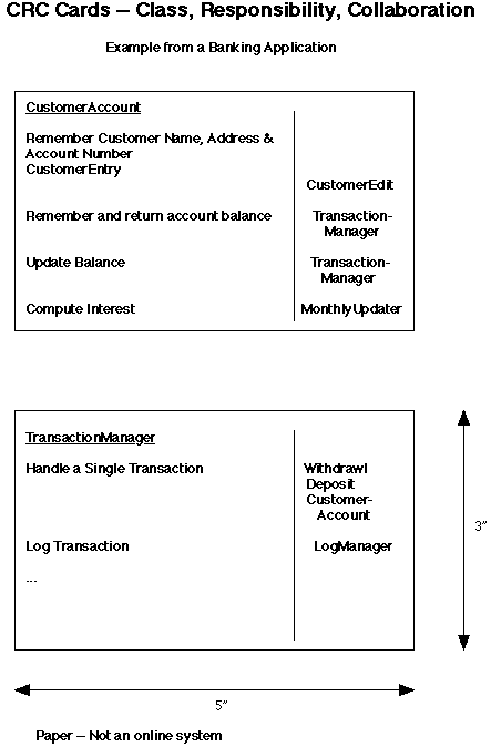
CRC cards are a very lightweight tool that can be used in initial analysis and design to help you decide what the objects and classes are. A CRC card is an ordinary 3 by 5 inch card that has the name of a class, the main responsibilities of that class and, for each responsibility which other classes must collaborate to carry out that responsibility. One of their main advantages is the fact that they contain little information and so can be easily discarded if they prove to be incorrect.

Note that the small size is important. Note also that it is important that this be done with paper documents, not an automated system. There is nothing to learn to use it, and little is lost when discarding a card. Since you have little investment in a particluar card, you are encouraged to experiment and discard failed tries.
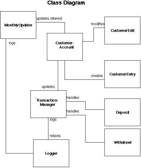
A Class Diagram shows the various relationships between the classes that you have in your system. The primary relationship is "association" though they may also be used to show aggregation and inheritance. Associations are tagged with the "roles" of the classes in the association. These can be drawn on paper or a white board. There are also elaborate software development tools that help you draw and maintain these and link them to other documentation and ultimately, to the code.

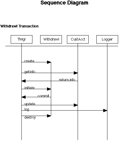
A Sequence Diagram shows the order of processing of some system change or update. In essence they show the message sequencing as messages flow from one object to another. There is generally (at least) one Sequence Diagram for each Use Case in your system. The vertical lines are (unscaled) time. There is one vertical line for each object that participates. It is labeled with the class of that object. The horizontal arrows show messages (and sometimes returns) sent from one object to another. If one arrow is drawn below another the first message is sent before the second. I.E. time flows downward. Sometimes an additional vertical line is drawn for each of the "actors" that must participate in the use case.

Note that you don't need sophisticated envoronments in which to create these. They can be done on a white board or with simple drawing tools. There are development environments in which these can be created and coordinated with other development steps, however.
Last Updated: October 22, 2001