Computer Graphics
|
|
Lecture
10 |
H&B Chapter 10 – Illumination Models and Surface Rendering
Light Sources
- Point
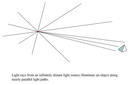
· Infinitely Distant
- Radial Intensity Attenuation
– (1/d2)
· Problems: Point Source with 1/d2 attenuation does not always produce realistic results.
· Produces too much intensity variation for near objects and not enough for distant.
· Directional Light Sources and Spotlight effects
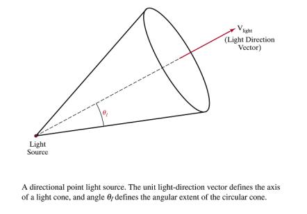
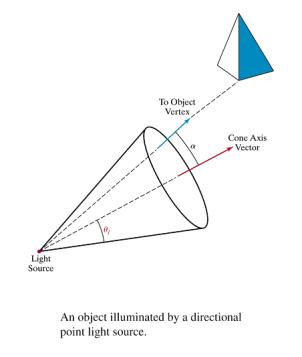
Angular Intensity Attenuation
![]()
Surface Lighting Effects
· Diffuse Reflection
· Specular Reflection
· Ambient
Simple Illumination Model
Surfaces
in real world environments receive light in 3 ways:
1.
Directly from existing light sources such as the sun or a
lit candle
2.
Light that passes and refracts through transparent objects
such as water or a glass vase
3.
Light reflected, bounced, or diffused from other exisiting
surfaces in the environment
Local Illumination
· Material
Models
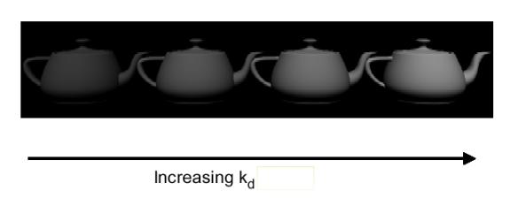
- Diffuse illumination
Lambert's
cosine law of reflection as shown in the above diagram:
1. n; a normal vector to the surface to be illuminated.
2. L, a vector from the surface
position that points towards the light source.
3. Il, an
intensity for a point light source.
4. kd ,
a diffuse reflection constant.
Equation
gives the brightness of a surface point in terms of the brightness of a light
source and its orientation relative to the surface normal vector, n,
![]()
·
I is the reflected
intensity
Measures how bright the surface is
at that point.
· Surface
brightness varies as a function of the angle between n and L
When n and L coincide, the
light source is directly overhead.
· I is at a
maximum and cosq = 1.
As the angle increases to 90o,
the cosine decreases the intensity to 0.
· All the
quantities in the equation are normalized between 0 and 1.
· I is
converted into frame buffer intensity values by multiplying by the number of
shades available.
· With 28
= 256 possible shades, we have 1 * 255, the brightest frame buffer intensity.
· For n and L at an angle of 45 o, I = cos 45 o * 256 =
181.
- An
image rendered with a Lambertian shader exhibits a dull, matte finish.
- It
appears as if it has been viewed by a coal miner with a lantern attached
to his helmet.
- In
reality, an object is not only subjected to direct illumination from the
primary light source Il , but
secondary scattered light from all remaining surfaces.
- Ambient illumination
·
Simple illuminated model is unable to directly accommodate
all scattered light
·
It is grouped together as independent intensity, Ia.
·
The formula becomes
![]()
·
Iaka is the ambient illumination term,
taking into account the additional environmental illumination, Ia, and the
ability of the object to absorb it, ka.
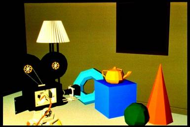
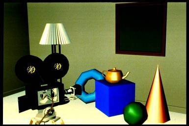
·
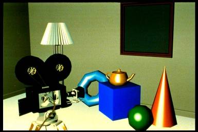
Below Figure: Only ambient illumination
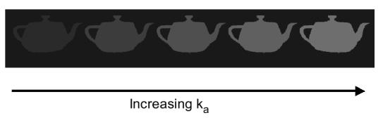
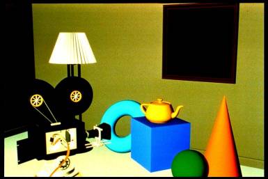
- Below Figure: Diffuse + ambient illumination
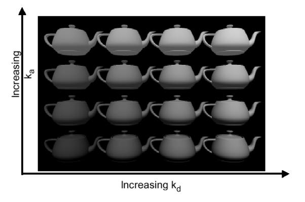
- Illumination
decreases from the light source by I/d2.
- Objects
at a greater distance from the light source receive less illumination and
appear darker.
- Above
equation is distance independent.
- Dividing
the Lambertian term by d2 would seem to get the physics right,
but it makes the intensity vary sharply over short distance.
- Modified
distance dependence is employed, giving
·
d is the distance from the light source to the object
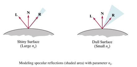
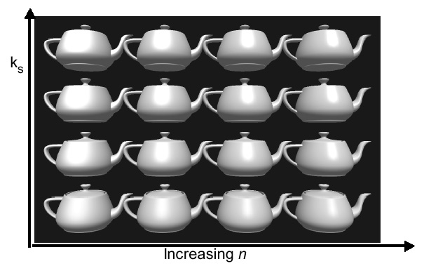
- Specular Highlights –
(Phong Reflection Model)
·
Regions of significant brightness, exhibited as spots or bands,
characterize objects that specularly reflect light.
·
Specular highlights originate from smooth, sometimes
mirrorlike surfaces
·
Fresnel equation is used to simulate this effect.
·
The Fresnel equation states that for a perfectly reflecting
surface the angle of incidence equals the angle of reflection.
·
Most objects are not perfect mirrors.
o
some angular scattering of light.
o
If the viewer increases the angle (a ) between
himself, the line of sight vector (S),
and the reflectance vector (R), the
bright spot gradually disappears.
o
Smooth surfaces scatter light less then rough surfaces.
o
This produces more localized highlights.
o
Building this effect into the lighting model gives
![]()
·
Specular reflectance term possesses a specular reflectance
constant, ks.
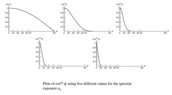
·
The cosine term is raised to the nth power.
o
Small values of n (e.g. 5) distribute the specular
highlights, characteristic of glossy paper.
o
High values of n (e.g. 50) are characteristic of metals.
1. Simple
Illumination Model
- Deficiencies
- point
light source
- no
interaction between objects
- ad
hoc, not based on model of light propagation
- Benefits
- fast
- acceptable
results
- hardware
support
How to Implement
Use the
following formula for diffuse + ambient illumination
![]() 0
£ q £ p/2
0
£ q £ p/2
1. Determine
polygon’s surface normal
2. Calculate cosine
of angle between surface normal and illumination vector
3. Scale to
frame buffer values between 0 and 255
1. Determine
polygon’s surface normal
i. Begin with
polygon vertices
|
|
x |
y |
z |
|
1 |
0.750 |
0.250 |
0.000 |
|
2 |
0.250 |
0.750 |
0.000 |
|
3 |
0.125 |
0.750 |
0.217 |
|
4 |
0.375 |
0.250 |
0.650 |
ii. Create
vectors P and Q
P = [ P2 –
P1] = [ Px Py Pz ] = [ x2 – x1 y2 –
y1 z2 – z1 ]
= [ -0.500 0.500 0.000
]
Q = [ P3 –
P2] = [ Qx Qy Qz ] = [ x2 – x2 y3 –
y2 z3 – z2 ]
= [ -0.125 0.000 0.217 ]
iii. Determine
length of P and Q
|P| = sqrt( Px2 + Py2 + Pz2 ) =
0.7071
|Q| = sqrt( Qx2 + Qy2 + Qz2 ) =
0.2500
iv. Normalize P
and Q
P(norm) = P
/ |P| = [ Px / |P| Py / |P|
Pz / |P| ]
= [ -0.7071 0.7071 0.0000 ]
Q(norm) = Q
/ |Q| = [ Qx / |Q| Qy /
|Q| Qz / |Q| ]
= [ -0.5000 0.0000 0.8660 ]
v. Calculate
normal vector using cross product:
|
n = PxQ |
|
|
nx = PyQz - PzQy |
|
|
ny = PzQx -PxQz |
|
|
nz = PxQy - PyQx |
|
n = [nx nx nx] = [0.1083 0.1083 0.0625]
vi. Normalize n
|
|n| = |
0.165359 |
|
||||
|
n(Norm) = |
[0.6547 |
0.6547 |
0.3780 ] |
||
vii. Create a
light vector
· Select a
point on the polygon surface and position for the light source
o A polygon
vertex may be selected or a position inside the polygon.
o Here we select
a position inside the polygon by calculating the midpoint between the 1st
and 3rd vertices
(xmid, ymid, zmid) = ( (x1 + x3)/2 , (y1 + y3)/2 , (z1 + z3)/2 )
|
= (0.438 |
0.500 |
0.108) |
o A position
for the light source is give as
|
x |
y |
z |
|
10 |
10 |
-5 |
Note: If observer is in –z direction than z value of light is also –z.
· Compute
light vector L
|
|
|
Lx |
Ly |
Lz |
|
|
Light
Vector (L) |
9.563 |
9.500 |
-5.108 |
|
|
|L| |
14.415 |
|
|
|
|
L(Norm) |
0.66338 |
0.65905 |
-0.35438 |
2. Calculate
cosine of angle between surface normal and illumination vector
i. Use dot
product formula:
|
nlL =
(nxLx+nyLy+nzLz)=|n||L|cosq |
Since n and L are
already normalized the formula reduces to
|
nlL =
(nxLx+nyLy+nzLz) = cosq |
||
|
= 0.7318 |
|
3. Scale to
frame buffer values between 0 and 255
0.7318 * 255 = int(186.6) = 186
Polygon Rendering Methods
Flat Shading (also known as faceted shading)
Shades each polygon of an object based on the angle between
the polygon's surface normal and the direction of the light source.
Disadvantage - it gives low-polygon models a
faceted look. Sometimes this look can be advantageous though, such as in
modeling boxy objects. Artists sometimes use flat shading to look at the
polygons of a solid model they are creating.
Gouraud Shading
Gouraud shading (Henri Gouraud, 1971) is used to achieve
smooth lighting on low-polygon surfaces using the Lambertian diffuse lighting
model.
1. Calculates the surface normals for the polygons.
2. Normals are then averaged for all the polygons that
meet at each vertex to produce a vertex normal.
3. Lighting computations are then performed to produce
intensities at vertices.
4. These intensities are interpolated along the
edges of the polygons.
5. The polygon is filled by lines drawn across it that
interpolate between the previously calculated edge intensities.
Advantage - Gouraud shading is superior to
flat shading which requires significantly less processing than Gouraud, but
gives low-polygon models a sharp, faceted look.
Phong Shading (Phong Interpolation Model)
·
An improved version of
Gouraud shading that provides a better approximation to the Phong shading
model.
·
Main problem with
Gouraud shading - when a specular highlight occurs near the center of a large triangle,
it will usually be missed entirely. Phong shading fixes the problem.
1. Calculate the surface normals at the vertices of
polygons in a 3D computer model.
2. Normals are then averaged for all the polygons that
meet at each vertex.
3. These normals are interpolated along the edges
of the polygons.
4. Lighting computations are then performed to produce
intensities at positions along scanlines.
OpenGL Lighting
Step 1: Enable Lighting
gl.glEnable(GL.GL_LIGHTING);
gl.glEnable(GL.GL_LIGHT0);
float [] lightColor = {1.0f, 1.0f, 1.0f,
1.0f};
gl.glLightfv(GL.GL_LIGHT0, GL.GL_DIFFUSE,
lightColor);
Step 2: Position the Light Source
float [] lightPosition = {5, 5, 5, 1};
gl.glLightfv(GL.GL_LIGHT0, GL.GL_POSITION,
lightPosition);
Step 3: Setup Material Properties
gl.glEnable(GL.GL_COLOR_MATERIAL);
gl.glColorMaterial(GL.GL_FRONT_AND_BACK,
GL.GL_DIFFUSE);
Step4: Add Normals
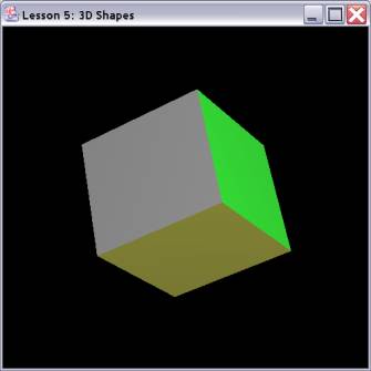
Sample Program:
Illuminated Cube
import
java.awt.*;
import
java.awt.event.*;
import
net.java.games.jogl.*;
public class
CubeLight
{
static Animator animator = null;
static class Renderer
implements GLEventListener,
KeyListener
{
private float rquad = 0.0f;
public void display(GLDrawable gLDrawable)
{
final GL gl = gLDrawable.getGL();
gl.glClear(GL.GL_COLOR_BUFFER_BIT |
GL.GL_DEPTH_BUFFER_BIT);
gl.glLoadIdentity();
gl.glTranslatef(0.0f, 0.0f, -15.0f);
gl.glRotatef(rquad, 0.5f, 1.0f, 0.5f);
gl.glBegin(GL.GL_QUADS); //
Draw A Quad
gl.glColor3f(0.0f,1.0f,0.0f);
gl.glNormal3f(0.0f,
1.0f, 0.0f);
gl.glVertex3f(
1.0f, 1.0f,-1.0f);
gl.glVertex3f(-1.0f,
1.0f,-1.0f);
gl.glVertex3f(-1.0f,
1.0f, 1.0f);
gl.glVertex3f(
1.0f, 1.0f, 1.0f);
gl.glColor3f(1.0f,0.5f,0.0f);
gl.glNormal3f(0.0f,
-1.0f, 0.0f);
gl.glVertex3f(
1.0f,-1.0f, 1.0f);
gl.glVertex3f(-1.0f,-1.0f,
1.0f);
gl.glVertex3f(-1.0f,-1.0f,-1.0f);
gl.glVertex3f(
1.0f,-1.0f,-1.0f);
gl.glColor3f(1.0f,0.0f,0.0f);
gl.glNormal3f(0.0f,
0.0f, 1.0f);
gl.glVertex3f(
1.0f, 1.0f, 1.0f);
gl.glVertex3f(-1.0f,
1.0f, 1.0f);
gl.glVertex3f(-1.0f,-1.0f,
1.0f);
gl.glVertex3f(
1.0f,-1.0f, 1.0f);
gl.glColor3f(1.0f,1.0f,0.0f);
gl.glNormal3f(0.0f,
0.0f, -1.0f);
gl.glVertex3f(
1.0f,-1.0f,-1.0f);
gl.glVertex3f(-1.0f,-1.0f,-1.0f);
gl.glVertex3f(-1.0f,
1.0f,-1.0f);
gl.glVertex3f(
1.0f, 1.0f,-1.0f);
gl.glColor3f(0.0f,0.0f,1.0f);
gl.glNormal3f(-1.0f,
0.0f, 0.0f);
gl.glVertex3f(-1.0f,
1.0f, 1.0f);
gl.glVertex3f(-1.0f,
1.0f,-1.0f);
gl.glVertex3f(-1.0f,-1.0f,-1.0f);
gl.glVertex3f(-1.0f,-1.0f,
1.0f);
gl.glColor3f(0.5f,0.5f,0.5f);
gl.glNormal3f(1.0f,
0.0f, 0.0f);
gl.glVertex3f(
1.0f, 1.0f,-1.0f);
gl.glVertex3f(
1.0f, 1.0f, 1.0f);
gl.glVertex3f(
1.0f,-1.0f, 1.0f);
gl.glVertex3f(
1.0f,-1.0f,-1.0f);
gl.glEnd();
gl.glFlush();
rquad += 0.15f;
}
public
void displayChanged(GLDrawable gLDrawable, boolean modeChanged, boolean
deviceChanged)
{
}
public void init(GLDrawable gLDrawable)
{
final GL gl = gLDrawable.getGL();
final GLU glu = gLDrawable.getGLU();
gl.glShadeModel(GL.GL_SMOOTH); // Enable Smooth Shading
gl.glClearColor(0.0f, 0.0f, 0.0f,
0.5f); // Black Background
gl.glClearDepth(1.0f); // Depth Buffer Setup
gl.glEnable(GL.GL_DEPTH_TEST); // Enables Depth Testing
gl.glDepthFunc(GL.GL_LEQUAL); // The Type Of Depth Testing To Do
gl.glMatrixMode(GL.GL_PROJECTION);
gl.glLoadIdentity();
gl.glTranslatef(0.0f, 0.0f, 0.0f);
glu.gluPerspective(20.0f, 1.0, 6.0,
20.0);
float [] lightPosition = {5, 5, 5, 1};
gl.glLightfv(GL.GL_LIGHT0, GL.GL_POSITION,
lightPosition);
gl.glMatrixMode(GL.GL_MODELVIEW);
gl.glLoadIdentity();
gl.glEnable(GL.GL_LIGHTING);
gl.glEnable(GL.GL_LIGHT0);
float
[] lightColor = {1.0f, 1.0f, 1.0f, 1.0f};
gl.glLightfv(GL.GL_LIGHT0,
GL.GL_DIFFUSE, lightColor);
gl.glEnable(GL.GL_COLOR_MATERIAL);
gl.glColorMaterial(GL.GL_FRONT_AND_BACK,
GL.GL_DIFFUSE);
gLDrawable.addKeyListener(this);
}
public void reshape(GLDrawable gLDrawable, int x, int y, int
width, int height)
{
}
public void keyPressed(KeyEvent e)
{
if (e.getKeyCode() ==
KeyEvent.VK_ESCAPE)
{
animator.stop();
System.exit(0);
}
}
public void keyReleased(KeyEvent e) {}
public void keyTyped(KeyEvent e) {}
}
public static void main(String[] args)
{
Frame frame = new Frame("Lesson 5: 3D
Shapes");
GLCanvas canvas =
GLDrawableFactory.getFactory().createGLCanvas(new GLCapabilities());
canvas.addGLEventListener(new Renderer());
frame.add(canvas);
frame.setSize(500, 500);
animator = new Animator(canvas);
frame.addWindowListener(new
WindowAdapter()
{
public void windowClosing(WindowEvent e)
{
animator.stop();
System.exit(0);
}
});
frame.show();
animator.start();
canvas.requestFocus();
}
}