Computer Graphics
|
|
Fall
2002 |
Lecture 15
H&B Chapter 14 – Illumination Models and Surface Rendering
Sections
14.1 – 14.2
Simple Illumination Model
Surfaces
in real world environments receive light in 3 ways:
1.
Directly from existing light sources such as the sun or a
lit candle
2.
Light that passes and refracts through transparent objects
such as water or a glass vase
3.
Light reflected, bounced, or diffused from other exisiting
surfaces in the environment
Local Illumination
· Material
Models
- Diffuse illumination
Lambert's
cosine law of reflection as shown in the above diagram:
1. n; a normal vector to the surface to be illuminated.
2. L, a vector from the surface
position that points towards the light source.
3. Il, an
intensity for a point light source.
4. kd ,
a diffuse reflection constant.
Equation gives
the brightness of a surface point in terms of the brightness of a light source
and its orientation relative to the surface normal vector, n,
![]() 0 £ q £ p/2
0 £ q £ p/2
·
I is the
reflected intensity
Measures how bright the surface is
at that point.
· Surface
brightness varies as a function of the angle between n and L
When n and L coincide, the
light source is directly overhead.
· I is at a
maximum and cosq = 1.
As the angle increases to 90o,
the cosine decreases the intensity to 0.
· All the
quantities in the equation are normalized between 0 and 1.
· I is
converted into frame buffer intensity values by multiplying by the number of
shades available.
· With 28
= 256 possible shades, we have 1 * 255, the brightest frame buffer intensity.
· For n and L at an angle of 45 o, I = cos 45 o * 256 =
181.
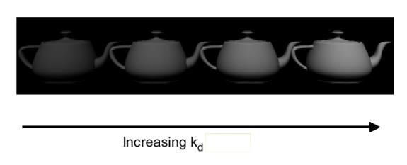
- An
image rendered with a Lambertian shader exhibits a dull, matte finish.
- It
appears as if it has been viewed by a coal miner with a lantern attached
to his helmet.
- In
reality, an object is not only subjected to direct illumination from the
primary light source Il , but
secondary scattered light from all remaining surfaces.
- Ambient illumination
·
Simple illuminated model is unable to directly accommodate
all scattered light
·
It is grouped together as independent intensity, Ia.
·
The formula becomes
![]() 0 £ q £ p/2
0 £ q £ p/2
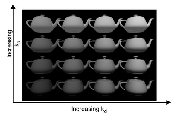
·
Iaka is the ambient illumination term,
taking into account the additional environmental illumination, Ia, and the
ability of the object to absorb it, ka.
·
Below Figure: Only ambient illumination
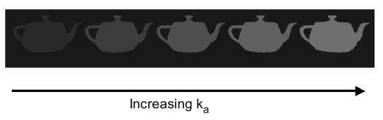
- Below Figure: Diffuse + ambient illumination
- Illumination
decreases from the light source by I/d2.
- Objects
at a greater distance from the light source receive less illumination and
appear darker.
- Above
equation is distance independent.
- Dividing
the Lambertian term by d2 would seem to get the physics right,
but it makes the intensity vary sharply over short distance.
- Modified
distance dependence is employed, giving
 0 £ q £ p/2
·
d is the distance from the light source to the object
- Specular Highlights
·
Regions of significant brightness, exhibited as spots or
bands, characterize objects that specularly reflect light.
·
Specular highlights originate from smooth, sometimes mirrorlike
surfaces
·
Fresnel equation is used to simulate this effect.
·
The Fresnel equation states that for a perfectly reflecting
surface the angle of incidence equals the angle of reflection.
·
Most objects are not perfect mirrors.
o
some angular scattering of light.
o
If the viewer increases the angle (a ) between
himself, the line of sight vector (S),
and the reflectance vector (R), the
bright spot gradually disappears.
o
Smooth surfaces scatter light less then rough surfaces.
o
This produces more localized highlights.
o
Building this effect into the lighting model gives
![]()
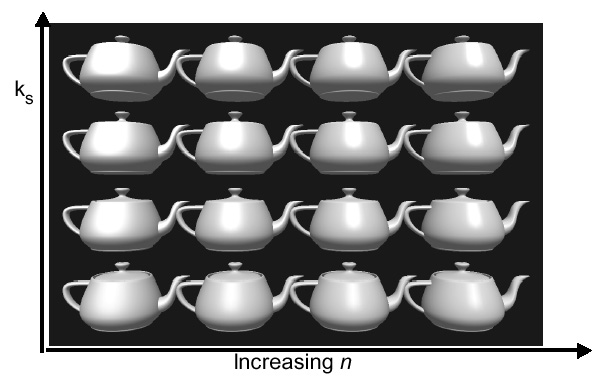
·
Specular reflectance term possesses a specular reflectance
constant, ks.
·
The cosine term is raised to the nth power.
o
Small values of n (e.g. 5) distribute the specular
highlights, characteristic of glossy paper.
o
High values of n (e.g. 50) are characteristic of metals.
1. Simple Illumination
Model
- Deficiencies
- point
light source
- no
interaction between objects
- ad
hoc, not based on model of light propagation
- Benefits
- fast
- acceptable
results
- hardware
support
How to Implement
Use the following
formula for diffuse + ambient illumination
![]() 0 £ q £ p/2
0 £ q £ p/2
1.
Determine polygon’s surface normal
2.
Calculate cosine of angle between surface normal and
illumination vector
3.
Scale to frame buffer values between 0 and 255
1.
Determine polygon’s surface normal
i. Begin with
polygon vertices
|
|
x |
y |
z |
|
1 |
0.750 |
0.250 |
0.000 |
|
2 |
0.250 |
0.750 |
0.000 |
|
3 |
0.125 |
0.750 |
0.217 |
|
4 |
0.375 |
0.250 |
0.650 |
ii. Create
vectors P and Q
P = [ P2 –
P1] = [ Px Py Pz ] = [ x2 – x1 y2 – y1 z2 – z1 ]
= [ -0.500 0.500 0.000
]
Q = [ P3 –
P2] = [ Qx Qy Qz ] = [ x2 – x2 y3 – y2 z3 – z2 ]
= [ -0.125 0.000 0.217 ]
iii. Determine
length of P and Q
|P| = sqrt( Px2 + Py2 + Pz2 ) = 0.7071
|Q| = sqrt( Qx2 + Qy2 + Qz2 ) = 0.2500
iv. Normalize P
and Q
P(norm) = P
/ |P| = [ Px / |P| Py / |P|
Pz / |P| ]
= [ -0.7071 0.7071 0.0000 ]
Q(norm) = Q
/ |Q| = [ Qx / |Q| Qy / |Q| Qz /
|Q| ]
= [ -0.5000 0.0000 0.8660 ]
v. Calculate
normal vector using cross product:
|
n = PxQ |
|
|
nx = PyQz - PzQy |
|
|
ny = PzQx -PxQz |
|
|
nz = PxQy - PyQx |
|
n = [nx nx nx] = [0.1083 0.1083 0.0625]
vi. Normalize n
|
|n| = |
0.165359 |
|
||||
|
n(Norm) = |
[0.6547 |
0.6547 |
0.3780 ] |
||
vii. Create a
light vector
· Select a
point on the polygon surface and position for the light source
o A polygon vertex
may be selected or a position inside the polygon.
o Here we
select a position inside the polygon by calculating the midpoint between the 1st
and 3rd vertices
(xmid, ymid, zmid) = ( (x1 + x3)/2 , (y1 + y3)/2 , (z1 + z3)/2 )
|
= (0.438 |
0.500 |
0.108) |
o A position
for the light source is give as
|
x |
y |
z |
|
10 |
10 |
-5 |
Note: If observer is in –z direction than z value of light is also –z.
· Compute
light vector L
|
|
|
Lx |
Ly |
Lz |
|
|
Light
Vector (L) |
9.563 |
9.500 |
-5.108 |
|
|
|L| |
14.415 |
|
|
|
|
L(Norm) |
0.66338 |
0.65905 |
-0.35438 |
2.
Calculate cosine of angle between surface normal and
illumination vector
i. Use dot
product formula:
|
nlL = (nxLx+nyLy+nzLz)=|n||L|cosq |
Since n and L are
already normalized the formula reduces to
|
nlL = (nxLx+nyLy+nzLz)
= cosq |
||
|
= 0.7318 |
|
3.
Scale to frame buffer values between 0 and 255
0.7318 * 255 = int(186.6) = 186