CS616 – Software Engineering II
|
|
Lecture 3
|
OBJECT-ORIENTED ANALYSIS AND DESIGN
1.1 Applying UML and Patterns in OOA/D
What does it mean to have a good object design? This book is a tool to
help developers and students learn core skills in object-oriented analysis and
design (OOA/D). These skills are essential for the creation of well-designed,
robust, and maintainable software using object technologies and languages such
as Java C++, Smalltalk.
The proverb "owning a hammer doesn't make one an architect" is
especially true with respect to object
technology. Knowing an object-oriented language (such as Java) is a necessary
but insufficient first step to create object systems. Knowing how to
"think in objects" is also critical. This is an introduction to OOA/D
while applying the Unified Modeling Language (UML), patterns, and the Unified
Process. It is not meant as an advanced text; it emphasizes mastery of the
fundamentals, such as how to assign responsibilities to objects, frequently
used UML notation, and common design patterns. At the same time, primarily in later chapters,
the material progresses to a few intermediate-level topics, such as framework
design. The book is not just about the UML. The UML is a standard
diagramming notation. As useful as it is to learn notation, there are more
critical object-oriented things to learn; specifically, how to think in
objects-how to design object-oriented systems. The UML is not OOA/D or a
method, it is simply notation. It is not so helpful to learn syntactically
correct UML diagramming and perhaps a UML CASE tool, but then not be able to
create an excellent design, or evaluate and improve an existing one. This is
the harder and more valuable skill. Consequently, this book is an introduction
to object design.
Yet, one needs a language for OOA/D and
"software blueprints," both as a tool of thought and as a form of
communication with others. Therefore, this book explores how to apply
the UML in the service of doing OOA/D, and covers frequently used UML notation.
But the emphasis is on helping people learn the art and science of building
object systems, rather than notation.
How should responsibilities be allocated to
classes of objects? How should objects interact? What classes should do what?
These are critical questions in the design of a system. Certain tried-and-true
solutions to design problems can be (and have been) expressed as best-practice
principles, heuristics, or patterns-named problem-solution formulas that
codify exemplary design principles. This book, by teaching how to apply
patterns, supports quicker learning and skillful use of these fundamental
object design idioms.
This introduction to OOA/D is illustrated in a
single case study that is followed throughout the book, going deep enough
into the analysis and design so
that some of the gory
details of what must be considered and solved in a realistic problem are
considered, and solved.
OOA/D (and all software
design) is strongly related to the prerequisite activity of requirements
analysis, which includes writing use cases. Therefore, the case
study begins with an introduction to these topics, even though they are not specifically
object-oriented. Given many possible activities from requirements through to
implementation, how should a developer or team proceed? Requirements analysis
and OOA/D needs to be presented in the context of some development process. In
this case, the well-known Unified Process is used as the sample
iterative development process within which these topics are introduced.
However, the analysis and design topics that are covered are common to many
approaches, and learning them in the context of the Unified Process does not
invalidate their applicability to other methods.
In conclusion, this book
helps a student or developer:
• Apply principles and patterns to create better object designs.
• Follow a set of common activities in analysis and design, based
on the
Unified Process as an example.
• Create frequently used diagrams in the UML notation.
It illustrates this in the
context of a single case study.
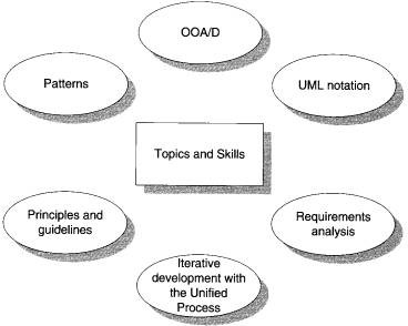
Figure 1.1 Topics and skills covered
Many
Other Skills Are Important
Building software involves myriad skills and steps
beyond requirements analysis, OOA/D, and object-oriented programming. For
example, usability engineering and user interface design are critical to
success; so is database design. However, this introduction emphasizes OOA/D,
and does not attempt to cover all topics in software development. It is one piece of a larger picture.
1.2
Assigning Responsibilities
There are many possible
activities and artifacts in introductory OOA/D, and a wealth of principles and
guidelines. Suppose we must choose a single practical skill from all the topics
discussed here-a "desert island" skill. What would it be?
A critical, fundamental
ability in OOA/D is to skillfully assign responsibilities to software
components.
Why?
Because it is one activity that must be performed-either while drawing a UML
diagram or programming-and it strongly influences the robustness,
maintainability,
and reusability of software components. Of course, there are other necessary
skills in OOA/D, but responsibility assignment is emphasized in this
introduction because it tends to be a challenging skill to master, and yet
vitally important. On a real project, a developer might not have the
opportunity to perform any other analysis or design activities-the "rush
to code" development process. Yet even in this situation, assigning responsibilities
is inevitable. Consequently, the design steps in this book emphasize principles
of responsibility assignment.
Nine fundamental principles
in object design and responsibility assignment are presented and applied. They
are organized in a learning aid called the GRASP patterns.
1.3 What
Is Analysis and Design?
Analysis emphasizes an investigation of the problem
and requirements, rather than a solution. For example, if a new computerized
library information system is desired, how will it be used? "Analysis"
is a broad term, best qualified, as in requirements analysis (an investigation
of the requirements) or object analysis (an investigation of the domain objects).
Design emphasizes a conceptual solution that
fulfills the requirements, rather than its implementation. For example, a
description of a database schema and software objects. Ultimately, designs can
be implemented.
As
with analysis, the term is best qualified', as in object or database
design
Analysis
and design have been summarized in the phase do the right thing (analysis),
and do the thing right (design).
1.4 What Is Object-Oriented Analysis and Design?
During object-oriented
analysis, there is an emphasis on finding and describing the objects-or
concepts-in the problem domain. For example, in the case of library informatlon system, some of the
concepts include Book, Library, and Patron.
During object-oriented
design, there is an emphasis on defining software objects and how they collaborate to fulfill the requirements. For
example in the library system, a Book software object may have a title
attribute and a getChapter method (see Figure 1.2).
Finally, during implementation
or object-oriented programming, design objects are implemented, such as a Book
class in Java.
1.5 An Example
Before diving into the details of requirements analysis and UOA/D, this
section presents a birds-eye view of a few key
steps and diagrams, using a simple example- a "dice game" in
which a player rolls two die. If the total is seven, they win - otherwise, they
lose.
Define
Use Cases
Requirements analysis may include a description of related domain
processes; these can be written as use cases.
Use
cases are not an object-oriented artifact-they are simply written stories. However,
they are a popular tool in requirements analysis and are an important part of
the Unified Process. For example, here is a brief version of the Play a Dice
Game use case:
Play a Dice Game: A player picks up and rolls the
dice. If the
dice face value total seven, they win; otherwise, they
lose.
Define
a Domain Model
Object-oriented analysis is concerned with creating a description of the
domain
from the perspective of classification by objects. A
decomposition of the domain
involves an identification of the concepts, attributes,
and associations that are
considered noteworthy. The result can be expressed in a
domain model, which
is illustrated in a set of diagrams that show domain
concepts or objects.
Figure
1.3 Partial domain model of the dice game.
This model illustrates the noteworthy concepts Player, Die, and DiceGame,
with their associations and attributes. Note that a domain model is not a
description of software objects; it is a visual-
ization of concepts in the real-world domain.
Define
Interaction Diagrams
Object-oriented design is
concerned with defining software objects and their collaborations. A common
notation to illustrate these collaborations is the interaction diagram.
It shows the flow of messages between software objects, and thus the invocation
of methods.
For example, assume that a software implementation of the dice game is
desired. The interaction
diagram in Figure 1.4 illustrates the essential step of
playing, by sending messages to instances of the DiceGame
and Die classes.
Figure
1.4 Interaction diagram illustrating messages between software objects.
Notice that although in the real world a player rolls the dice,
in the software
design the DiceGame
object "rolls" the dice (that is, sends messages to Die
objects). Software object
designs and programs do take some inspiration from
real-world domains, but they
are not direct models or simulations of the real
world.
Define Design Class Diagrams
In addition to a dynamic view of collaborating
objects shown in interaction diagrams, it is useful to create a static
view of the class definitions with a design class diagram. This
illustrates the attributes and methods of the classes.
For
example, in the dice game, an inspection of the interaction diagram leads to the
partial design class diagram shown in Figure 1.5. Since a play message
is sent to a DiceGame object, the DiceGame class requires a play
method, while class Die requires a roll and getFaceValue
method.
In contrast to the domain
model, this diagram does not illustrate real-world concepts; rather, it shows
software classes.
Figure
1.5 Partial design class diagram.
Summary
The
dice game is a simple problem, presented to focus on a few steps and artifacts
in analysis and design. To keep the introduction simple, not all the illustrated
UML notation was explained. Future chapters explore analysis and design and
these artifacts in closer detail.
1.6 The UML
To
quote:
The Unified Modeling Language (UML) is a language for
specifying, visualizing, constructing, and documenting the artifacts of software
systems, as well as for business modeling and other non-software systems [OMG01].
The UML has emerged as the de
facto and de jure standard diagramming notation for object-oriented modeling.
It started as an effort by Grady Booch and Jim Rumbaugh in 1994 to combine the
diagramming notations from their two popular methods-the Booch and OMT (Object
Modeling Technique) methods. They were later joined by Ivar Jacobson, the
creator of the Objectory method, and as a group came to be known as the three
amigos. Many others contributed to the UML, perhaps most notably Cris Kobryn,
a leader in its ongoing refinement. The UML was adopted in 1997 as a standard
by the OMG (Object Management Group, an industry standards body), and has
continued to be refined in new OMG UML versions.
This book does not cover
every minute aspect of the UML, which is a large body of notation (some say,
too large1). It focuses on diagrams which are frequently used, the most
commonly used features within those diagrams, and core notation that is
unlikely to change in future versions of the UML.
Why
Won't We See Much UML for a Few Chapters?
This is not just a UML notation book, but one that explores the larger
picture of applying the UML, patterns, and an iterative process in the context
of software development. The UML is primarily applied during OOA/D, which is
normally preceded by requirements analysis. Therefore, the initial chapters
present an introduction to the important topics of use cases and requirements
analysis, which are then followed by chapters on OOA/D and more UML details.
Chapter 2
ITERATIVE
DEVELOPMENT AND THE UNIFIED PROCESS
Objectives
Provide
motivation for the content and order of subsequent chapters.
Define
an iterative and adaptive process.
Define
fundamental concepts in the Unified Process.
Introduction
Iterative
development is a skillful approach to software development, and lies at
the
heart of how OOA/D is presented in this book. The Unified Process is an
example
iterative process for projects using OOA/D, and it shapes the book's
presentation.
Consequently, it is useful to read this chapter so that these core
concepts
and their influence on the book's structure are clear.
This
chapter summarizes a few key ideas; please see Chapter 37 for further dis-
cussion
of the UP and iterative process practices.
Informally,
a software development process describes an approach to build-
ing,
deploying, and possibly maintaining software. The Unified Process
[JBR99]
has emerged as a popular software development process for building
object-oriented
systems. In particular, the Rational Unified Process or RUP
[KruchtenOO],
a detailed refinement of the Unified Process, has been widely
adopted.
The
Unified Process (UP) combines commonly accepted best practices, such as
an
iterative lifecycle and risk-driven development, into a cohesive and well-doc-
umented
description. Consequently, it is used in this book as the example pro-
cess
within which to introduce OOA/D.
This
book starts with an introduction to the UP for two reasons:
1. The UP is an iterative process. Iterative
development is a valuable practice
that
influences how this book introduces OOA/D, and how it is best practiced.
2. UP practices provide an example structure
to talk about how to do—and how to
learn—OOA/D.
This
text presents an introduction to the UP, not complete coverage. It emphasizes
common ideas and artifacts related to an introduction to OOA/D
and
requirements analysis.
What
If I Don't Care About the UP?
The UP is used as an example process
within which to explore requirements
analysis and OOA/D, since it is
necessary to introduce the subject in the context
of some process, and the UP (or the
RUP refinement) is relatively widely used.
Also, the UP presents common
activities and best practices. Nevertheless, the
central ideas of this book—such as
use cases and design patterns—are indepen-
dent of any particular process, and
apply to many.
The
Most Important UP Idea: Iterative Development
The UP promotes several best
practices, but one stands above the others: itera-
tive development. In this approach,
development is organized into a series of
short, fixed-length (for example,
four week) mini-projects called iterations; the
outcome of each is a tested,
integrated, and executable system. Each iteration
includes its own requirements
analysis, design, implementation, and testing
activities.
The iterative lifecycle is based on
the successive enlargement and refinement of
a system through multiple iterations,
with cyclic feedback and adaptation as
core drivers to converge upon a
suitable system. The system grows incremen-
tally over time, iteration by
iteration, and thus this approach is also known as
iterative and incremental development
(see Figure 2.1).
Early
iterative process ideas were known as spiral development and evolutionary
development [Boehm88, Gilb88].
Requirements
Design
Implementation
&
Test
& Integration
& More Design
Final
Integration
& System Test
Requirements
Time
5
Design
Implementation
&
Test
& Integration
& More Design
Final
Integration
& System Test
Feedback
from
iteration
N leads to
refinement
and
adaptation
of the
requirements
and
design
in iteration
N+1.
4
weeks (for example)
Iterations
are fixed in
length,
or timeboxed.
The
system grows
incrementally.
Figure
2.1 Iterative and incremental development.
Example
As
an example (not a recipe), in a two-week iteration half-way through a
project,
perhaps Monday is spent primarily on distributing and clarifying the
tasks
and requirements of the iteration, while one person reverse-engineers
the
last iteration's code into UML diagrams (via a CASE tool), and prints
and
displays noteworthy diagrams. Tuesday is spent at whiteboards doing
pair
design work drawing rough UML diagrams captured on digital cameras,
and
writing some pseudocode and design notes. The remaining eight days
are
spent on implementation, testing (unit, acceptance, usability, ...), further
design,
integration, daily builds, system testing, and stabilization of the par-
tial
system. Other activities include demonstrations and evaluations with
stakeholders,
and planning for the next iteration.
Notice
in this example that there is neither a rush to code, nor a long drawn-out
design
step that attempts to perfect all details of the design before program-
ming.
A "little" forethought regarding the design with visual modeling
using
rough
and fast UML drawings is done; perhaps a half or full day by developers
doing
design work in pairs.
The
result of each iteration is an executable but incomplete system; it is not
ready
to deliver into production. The system may not be eligible for production
deployment
until after many iterations; for example, 10 or 15 iterations.
The output of an iteration is not an
experimental or throw-away prototype, and
iterative development is not
prototyping. Rather, the output is a production-
grade subset of the final system.
Although, in general, each iteration
tackles new requirements and incremen-
tally extends the system, an iteration may occasionally revisit existing
software
and improve it; for example, one
iteration may focus on improving the perfor-
mance of a subsystem, rather than
extending it with new features.
Embracing
Change: Feedback and Adaptation
The subtitle of one book that
discusses iterative development is Embrace
Change [BeckOO]. This phrase is
evocative of a key attitude of iterative develop-
ment: Rather than fighting the
inevitable change that occurs in software devel-
opment by trying (usually
unsuccessfully) to fully and correctly specify, freeze,
and "sign off" on a frozen
requirement set and design before implementation,
iterative development is based on an attitude of embracing
change and adapta-
tion as unavoidable and indeed
essential drivers.
This is not to say that iterative
development and the UP encourages an uncon-
trolled and reactive "feature
creep"-driven process. Subsequent chapters explore
how the UP balances the need—on the
one hand—to agree upon and stabilize a
set of requirements, with—on the
other hand—the reality of changing require-
ments, as stakeholders clarify their vision or the marketplace
changes.
Each iteration involves choosing a
small subset of the requirements, and quickly
designing, implementing, and testing.
In early iterations the choice of require-
ments and design may not be exactly
what is ultimately desired. But the act of
swiftly taking a small step, before
all requirements are finalized, or the entire
design is speculatively defined,
leads to rapid feedback—feedback from the
users, developers, and tests (such as
load and usability tests).
This early feedback is worth its
weight in gold; rather than speculating on the
correct requirements or design, the
feedback from realistic building and testing
something provides crucial practical
insight and an opportunity to modify or
adapt understanding of the
requirements or design. End-users have a chance to
quickly see a partial system and say,
"Yes, that's what I asked for, but now that I
try it, what I really want is
something slightly different."1 This "yes...but" pro-
cess is not a sign of failure;
rather, early and frequent structured cycles of
"yes...buts" are a skillful
way to make progress and discover what is of real value
to the stakeholders. Yet, as
mentioned, this is not an endorsement of chaotic and
reactive development in which
developers continually change direction—a mid-
dle way is possible.
In addition to requirements
clarification, activities such as load testing will
prove if the partial design and
implementation are on the right path, or if in the
next
iteration, a change in the core architecture is required. Better to resolve
and
prove the risky and critical design decisions early rather than late—and
iterative
development provides the mechanism for this.
Consequently,
work proceeds through a series of structured build-feedback-
adapt
cycles. Not surprisingly, in early iterations the deviation from the "true
path"
of the system (in terms of its final requirements and design) will be larger
than
in later iterations. Over time, the system converges towards this path, as
illustrated
in Figure 2.2.
Early
iterations are farther from the "true
path"
of the system. Via feedback and
adaptation,
the system converges towards
the
most appropriate requirements and
design.
In
late iterations, a significant change in
requirements
is rare, but can occur. Such
late
changes may give an organization a
competitive
business advantage.
one iteration of design,
implement,
integrate, and test
Figure 2.2 Iterative feedback and
adaptation leads towards the desired system.
The requirements and design
instability lowers over time.
Benefits
of Iterative Development
Benefits
of iterative development include:
• early rather than late mitigation of high
risks (technical, requirements,
objectives, usability, and so forth)
• early visible progress
• early feedback, user engagement, and
adaptation, leading to a refined sys-
tem that more closely meets the real needs
of the stakeholders
• managed complexity; the team is not
overwhelmed by "analysis paralysis" or
very long and complex steps
• the learning within an iteration can be
methodically used to improve the
development process itself, iteration by
iteration
Iteration
Length and Timeboxing
The UP (and experienced iterative
developers) recommends an iteration length
between two and six weeks. Small
steps, rapid feedback, and adaptation are
central ideas in iterative
development; long iterations subvert the core motiva-
tion for iterative development and
increase project risk. Much less than two
weeks, and it is difficult to
complete sufficient work to get meaningful through-
put and feedback; much more than six
or eight weeks, and the complexity
becomes rather overwhelming, and feedback is delayed. A very
long iteration
misses the point of iterative
development. Short is good.
A key idea is that iterations are
timeboxed, or fixed in length. For example, if
the next iteration is chosen to be four weeks long, then the
partial system should
be integrated, tested, and stabilized
by the scheduled date—date slippage is dis-
couraged. If it seems that it will be
difficult to meet the deadline, the recom-
mended response is to remove tasks or
requirements from the iteration, and
include them in a future iteration,
rather than slip the completion date. Chapter
37 summarizes reasons for timeboxing.
Massive teams (for example, several hundred developers) may
require longer
than six-week iterations to
compensate for the overhead of coordination and
communication; but no more than three
to six months is recommended. For
example, the successful replacement in the 1990s of the
Canadian air traffic
control system was developed with an
iterative lifecycle and other UP practices.
It involved 150 programmers and was
organized into six-month iterations.2 But
note that even in the case of an
overall six-month project iteration, a subsystem
team of 10 or 20 developers can break
down their work into a series of six one-
month iterations.
A six-month iteration is the exception
for massive teams, not the rule. To reiter-
ate, the UP recommends that normally
an iteration should be between two and
six weeks in duration.
Additional
UP Best Practices and Concepts
The
central idea to appreciate and practice in the UP is short timeboxed itera-
tive,
adaptive development.
Another
implicit, but core, UP idea is the use of object technologies, including
OOA/D
and object-oriented programming.
Some additional best practices and
key concepts in the UP include:
•
tackle high-risk and high-value issues in early iterations
•
continuously engage users for evaluation, feedback, and requirements
•
build a cohesive, core architecture in early iterations
•
continuously verify quality; test early, often, and realistically
•
apply use cases
•
model software visually (with the UML)
•
carefully manage requirements
•
practice change request and configuration management
See Chapter 37 for a more detailed
description of these practices.
The
UP Phases and Schedule-Oriented Terms
A UP project organizes the work and
iterations across four major phases:
1.
Inception— approximate vision, business case, scope, vague estimates.
2.
Elaboration—refined vision, iterative implementation of the core
architec-
ture, resolution of high risks,
identification of most requirements and scope,
more realistic estimates.
3.
Construction—iterative implementation of the remaining lower risk and
easier elements, and preparation
for deployment.
4.
Transition—beta tests, deployment.
These phases are more fully defined
in subsequent chapters.
This is not the old
"waterfall" or sequential lifecycle of first defining all the
requirements, and then doing all or
most of the design.
Inception is not a requirements
phase; rather, it is a kind of feasibility phase,
where just enough investigation is
done to support a decision to continue or
stop.
Similarly, elaboration is not the
requirements or design phase; rather, it is a
phase where the core architecture is
iteratively implemented, and high risk
issues are mitigated.
Figure 2.3 illustrates common
schedule-oriented terms in the UP. Notice that
one development cycle (which ends in
the release of a system into production) is
composed of many iterations.
The
UP Disciplines (was Workflows)
The
UP describes work activities, such as writing a use case, within disciplines
(originally
called workflows).3 Informally, a discipline is a set of activities (and
related
artifacts) in one subject area, such as the activities within requirements
analysis.
In the UP, an artifact is the general term for any work product: code,
Web
graphics, database schema, text documents, diagrams, models, and so on.
There
are several disciplines in the UP; this book focuses on some artifacts in
the
following three:
• Business Modeling—When developing a single
application, this includes
domain object modeling. When engaged in large-scale
business analysis or
business process reengineering, this
includes dynamic modeling of the busi-
ness processes across the entire
enterprise.
• Requirements—Requirements analysis for an
application, such as writing
use cases and identifying non-functional
requirements.
• Design—All aspects of design, including the
overall architecture, objects,
databases, networking, and the like.
3.
In 2001, the old UP term "workflow" was replaced by the new term
"discipline" in
order to harmonize with an international
standardization effort called the OMG
SPEM; because of its prior meaning in the
UP, many continue to use the term work-
flow to mean discipline, although this is
not strictly correct. The term "workflow" took
on a new but slightly different meaning
within the UP: On a particular project, it is a
particular sequence of activities (perhaps
across disciplines)—a flow of work.
A
longer list of UP disciplines is shown in Figure 2.4.
Figure 2.4 UP disciplines.4
In the UP, Implementation means
programming and building the system, not
deployment. The Environment
discipline refers to establishing the tools and
customizing the process for the project—that
is, setting up the tool and process
environment.
Disciplines
and Phases
As illustrated in Figure 2.4, during
one iteration work goes on in most or all dis-
ciplines. However, the relative
effort across these disciplines changes over time.
Early iterations naturally tend to
apply greater relative emphasis to require-
ments and design, and later ones
less so, as the requirements and core design
stabilize through a process of
feedback and adaptation.
Relating this to the UP phases
(inception, elaboration, ...), Figure 2.5 illustrates
the changing relative effort with
respect to the phases; please note these are
suggestive, not literal. In
elaboration, for example, the iterations tend to have a
relatively
high level of requirements and design work, although definitely some
implementation
as well. During construction, the emphasis is heavier on imple-
mentation
and lighter on requirements analysis.
Book
Structure and UP Phases and Disciplines
With respect to the phases and
disciplines, what is the focus of the case study?
Answer:
The
case study emphasizes the inception and elaboration phase. It focuses
on
some artifacts in the Business Modeling, Requirements, and Design disci-
plines,
as this is where requirements analysis, OOA/D, patterns, and the
UML
are primarily applied.
The
earlier chapters introduce activities in inception; later chapters explore sev-
eral
iterations in elaboration. The following list and Figure 2.6 describe the
organization
with respect to the UP phases.
1. The inception phase chapters introduce the
basics of requirements analysis.
2. Iteration 1 introduces fundamental OOA/D and
how to assign responsibili-
ties to objects.
3. Iteration 2 focuses on object design,
especially on introducing some high-use
"design patterns."
4. Iteration 3 introduces a variety of
subjects, such as architectural analysis
and framework design.
Process
Customization and the Development Case
Optional
Artifacts
Some UP practices and principles are
invariant, such as iterative and risk-
driven development, and continuous
verification of quality.
However, a key insight into the UP is that all activities and
artifacts (models,
diagrams, documents, ...) are
optional—well, maybe not the code! The set of pos-
sible artifacts described in the UP
should be viewed like a set of medicines in a
pharmacy. Just as one does not
indiscriminately take many medicines, but
matches the choice to the ailment,
likewise on a UP project, a team should select
a small subset of artifacts that
address its particular problems and needs. In
general, focus on a small set of
artifacts that demonstrate high practical value.
The
Development Case
The choice of UP artifacts for a
project may be written up in a short document
called the Development Case (an
artifact in the Environment discipline). For
example, Table 2.1 could be the
Development Case describing the artifacts for
the "NextGen Project" case
study explored in this book.
Subsequent chapters describe the
creation of some of these artifacts, including
the Domain Model, Use-Case Model, and
Design Model.
The example artifacts presented in
this case study are by no means sufficient
for, or suitable for, all projects.
For example, a machine control system may ben-
efit from doing many state diagrams.
A Web-based e-commerce system may
require a focus on user interface
prototypes. A "green-field" new development
The
Agile UP
Methodologists speak of processes as heavy
vs. light, and predictive vs. adaptive.
A
heavy process is a pejorative term meant to suggest one with the following
qualities
[FowlerOO]:
• many artifacts created in a bureaucratic
atmosphere
• rigidity and control
• elaborate, long-term, detailed planning
• predictive rather than adaptive
A
predictive process is one that attempts to plan and predict the activities
and
resource (people) allocations in detail over a relatively long time span, such
as
the majority of a project. Predictive processes usually have a
"waterfall" or
sequential
lifecycle—first, defining all the requirements; second, denning a
detailed
design; and third, implementing. In contrast, an adaptive process is
one
that accepts change as an inevitable driver and encourages flexible adapta-
tion;
they usually have an iterative lifecycle. An agile process implies a light
and
adaptive process, nimble in response to changing needs.
The
UP was not meant by its authors to be either heavy or predictive, although
its
large optional set of activities and artifacts have understandably led to that
project
has very different design artifact needs than a systems integration
project.
Table
2.1 Sample Development Case of UP artifacts, s - start; r - refine
3The
Agile UP
Methodologists
speak of processes as heavy vs. light, and predictive vs. adaptive.
A
heavy process is a pejorative term meant to suggest one with the following
qualities
[FowlerOO]:
• many artifacts created in a bureaucratic
atmosphere
• rigidity and control
• elaborate, long-term, detailed planning
• predictive rather than adaptive
A
predictive process is one that attempts to plan and predict the activities
and
resource (people) allocations in detail over a relatively long time span, such
as
the majority of a project. Predictive processes usually have a
"waterfall" or
sequential
lifecycle—first, denning all the requirements; second, denning a
detailed
design; and third, implementing. In contrast, an adaptive process is
one
that accepts change as an inevitable driver and encourages flexible adapta-
tion;
they usually have an iterative lifecycle. An agile process implies a light
and
adaptive process, nimble in response to changing needs.
The
UP was not meant by its authors to be either heavy or predictive, although
its
large optional set of activities and artifacts have understandably led to that
impression in some. Rather, it was
meant to be adopted and applied in the spirit
of an agile process—agile UP. Some
examples of how this applies:
•
Prefer a small set of UP activities and artifacts. Some projects will
benefit
from more than others, but, in
general, keep it simple.
•
Since the UP is iterative, requirements and designs are not completed
before implementation. They
adaptively emerge through a series of itera-
tions, based on feedback.
•
There isn't a detailed plan for the entire project. There is a high
level plan
(called the Phase Plan) that
estimates the project end date and other major
milestones, but it does not
detail the fine-grained steps to those milestones.
A detailed plan (called the
Iteration Plan) only plans with greater detail
one iteration in advance.
Detailed planning is done adaptively from itera-
tion to iteration. Please see
Chapter 36 for some comments on planning iter-
ative projects, and the justification for this approach.
The case study emphasizes a
relatively small number of artifacts, and iterative
development, in the spirit of an
agile UP.
The
Sequential "Waterfall" Lifecycle
In contrast to the iterative lifecycle of the UP, an old
alternative was the sequen-
tial, linear, or
"waterfall" lifecycle [Royce70]. In common usage, it defined steps
similar to the following:
1.
Clarify, record, and commit to a set of complete and frozen
requirements.
2.
Design a system based on these requirements.
3.
Implement, based on the design.
A two year study reported in the MIT
Sloan Management Review of successful
software projects identified four
common factors for success; iterative develop-
ment, rather than a waterfall
process, was first on the list [MacCormackOl].5
A brief description of its problems,
and how they are mitigated by iterative
development, is presented in Chapter
37.
You
Know You Didn't Understand the UP When...
Here
are some signs that indicate when you have not understood what it means
to
adopt the UP and iterative development in the agile spirit intended by the
UP.
• You think that inception = requirements,
elaboration = design, and con-
struction = implementation (that is,
superimposing a waterfall lifecycle on
to the UP).
• You think that the purpose of elaboration is
to fully and carefully define
models, which are translated into code
during construction.
• You try to define most of the requirements
before starting design or imple-
mentation.
• You try to define most of the design before
starting implementation; you try
to fully define and commit to an
architecture before iterative programming
and testing.
• A "long time" is spent doing
requirements or design work before program-
ming starts.
• You believe that a suitable iteration length
is four months long, rather than
four weeks long (excluding projects with
hundreds of developers).
• You think UML diagramming and design
activities are a time to fully and
accurately define designs and models in
great detail, and of programming as
a simple mechanical translation of these
into code.
• You think that adopting the UP means to do
many of the possible activities
and create many documents, and thinks of
or experiences the UP as a for-
mal, fussy process with many steps to be
followed.
• You try to plan a project in detail from
start to finish; you try to specula-
lively predict all the iterations, and
what should happen in each one.
• You want believable plans and estimates for projects
before the elaboration
phase is finished.
CASE STUDY: THE NEXTGEN POS SYSTEM
Introduction
This chapter briefly
describes the case study. If you understand the problem domain, it may be
skipped. Indeed, this problem was chosen because it is familiar, but rich with
interesting design and architectural problems, and thus allows one to
concentrate on how to do analysis and design, rather than explain the problem
and domain.
The NextGen POS System
The case study is the NextGen point-of-sale (POS) system.
In this apparently straightforward problem domain, we shall see that there are
very interesting requirement and design problems to solve. In addition, it is a
realistic problem; organizations really do write POS systems using object
technologies.
A POS system is a
computerized application used (in part) to record sales and handle payments; it
is typically used in a retail store. It includes hardware components such as a
computer and bar code scanner, and software to run the system. It interfaces to
various service applications, such as a third-party tax calculator and
inventory control. These systems must be relatively fault-tolerant; that is,
even if remote services are temporarily unavailable (such as the inventory
system), they must still be capable of capturing sales and handling at least
cash payments (so that the business is not crippled).
A POS system increasingly
must support multiple and varied client-side terminals and interfaces. These
include a thin-client Web browser terminal, a regular personal computer with
something like a Java Swing graphical user interface, touch screen input,
wireless PDAs, and so forth. Furthermore, we are creating a commercial POS system
that we will sell to different clients with disparate needs in terms of
business rule processing.
Each client will desire a unique set of logic to execute at certain
predictable points in scenarios of using the system, such as when a
new sale is initiated or when a new line item is added. Therefore, we will
need a mechanism to provide this flexibility and customization. Using an iterative development strategy, we are going to proceed
through requirements, object-oriented
analysis, design, and implementation.
Architectural Layers and
Case Study Emphasis
A typical object-oriented information system is designed in terms of
several architectural layers or
subsystems (see Figure 3.1). The following is not a com plete list, but provides an example:
• User Interface—graphical
interface; windows.
• Application
Logic and Domain Objects-software objects representing domain concepts (for example, a
software class named Sale) that fulfill application requirements.
• Technical Services—general purpose
objects and subsystems that provide supporting technical services, such as interfacing
with a database or error logging. These services are usually
application-independent and reusable across several systems.
The
NextGen case study primarily emphasizes the problem domain objects, allo-
cating responsibilities to
them to fulfill the requirements of the application.
Object-oriented design is
also applied to create a technical service subsystem tor
interfacing with a database.
In this design approach, the
UI layer has very little responsibility; it is said to
be thin. Windows do not
contain code that performs application logic or process-
ing.
Rather, task requests are forwarded on to other layers.
The Book's Strategy: Iterative Learning and Development
This book is organized to
follow an iterative development strategy OOA/D is applied to the NextGen POS system in multiple iterations; the
first iteration is for some core functions. Later iterations expand the
functionality of the system (see Figure 3.2). In conjunction with iterative
development, the presentation of analysis and design topics, UML
notation, and patterns are introduced iteratively and incrementally. In the first
iteration, a core set of analysis and design topics and notation is presented.
The second iteration expands into new ideas UML notation, and patterns. And
likewise in the third iteration.
Chap 4
Introduction
This chapter defines the inception phase of a project. If process ideas
are not your priority, or you prefer to first focus on learning the main
practical activity in this phase—use case modeling—then this chapter can be
skipped. Most projects require a short initial step in which the following
kinds of questions are explored:
• What is the vision and business case for this project?
• Feasible?
• Buy and/or
build?
• Rough estimate of cost: Is it $10K-100K or in the millions?
• Should we proceed or stop?
Defining the vision and
obtaining an order-of-magnitude (unreliable) estimate
necessitates doing some
requirements exploration. However, the purpose of the
inception step is not to
define all the requirements, or generate a believable esti-
mate or project plan. At the
risk of over-simplification, the idea is to do just
enough investigation to form
a rational, justifiable opinion of the overall pur-
pose and feasibility of the potential new system, and
decide if it is worthwhile to
invest
in deeper exploration (the purpose of the elaboration phase).
Thus,
the inception phase should be relatively short for most projects, such as
one or a few weeks long. Indeed, on many projects, if
it is more than a week long,
then the point of inception has been missed: It is to
decide if the project is worth
a serious investigation
(during elaboration), not to do that investigation.
Inception: An Analogy
In
the oil business, when a new field is being considered, some of the steps
include:
1. Decide if there is enough evidence or a business case to even
justify explor-
atory drilling.
2. If so, do measurements and exploratory drilling.
3. Provide scope and estimate information.
4. Further steps...
The inception phase is like step one in this analogy.
In step one people do not
predict how much oil there is, or the cost or effort
to extract it. It is premature—
there is insufficient information. Although it would
be nice to be able to answer
"how much" and
"when" questions without the cost and effort of the exploration,
in the oil business it is understood to not be
realistic.
In UP terms, the realistic
exploration step is the elaboration phase. The preced-
ing inception phase is akin
to a feasibility study to decide if it is even worth
investing in exploratory
drilling. Only after exploration (elaboration) do we have
the data and insight to make
somewhat believable estimates and plans. There-
fore, in iterative
development and the UP, plans and estimates are not to be con-
sidered reliable in the
inception phase. They merely provide an order-of-
magnitude sense of the
level of effort, to aid the decision to continue or not.
Inception
May Be Very Brief
The intent of inception is
to establish some initial common vision for the objectives of the project,
determine if it is feasible, and decide if it is worth some serious investigation in elaboration. If it has been
decided beforehand that the project will definitely be done, and it is clearly feasible (perhaps because
the team has done projects like this before), then the inception phase
will be especially brief. It may include the first requirements workshop, planning for the first iteration, and then
quickly moving forward to elaboration.
What
Artifacts May Start in Inception?
Table 4.1 lists common inception (or early
elaboration) artifacts and indicates
the issues they address. Subsequent chapters will examine some of these
in
greater detail, especially the Use-Case Model. A key
insight regarding iterative
development is to appreciate that these are only
partially completed in this
phase, will be refined in later iterations, and should not even be created
unless
it is deemed likely they will add real practical value.
And since it is inception,
the investigation and artifact content should be light.
For example, the Use-Case Model (to be described in
following chapters) may list
the names of most of the expected use cases and
actors, but perhaps only
describe 10% of the use cases in detail—done in the
service of developing a
rough high-level vision of the system scope, purpose,
and risks.
Note that some programming work may occur in inception
in order to create
Table 4.1 Sample inception
artifacts.
t-These
artifacts are only partially completed in this phase. They will be itera-
tively refined in subsequent iterations. Name capitalization implies
it is an offi-
cially named UP artifact.
Isn't
That a Lot of Documentation?
Recall that artifacts should be considered optional. Choose to create
only those
that really add value for the project, and
drop them if their worth is not proved.
The point of an artifact is not the document
or diagram itself, but the thinking,
analysis, and proactive readiness (and then
its recording, to avoid re-invention
or having to repeat things verbally). As
General Eisenhower
said, "In preparing
for battle I have always found that plans are
useless, but planning indispens-
able" [Nixon90,BFOO].
Record artifacts digitally and
online—available on the project's website—rather
than on paper.
Note also that UP artifacts from previous
projects can be reused on later ones. It
is
common for there to be many similarities in risk, project management, test-
ing, and environment artifacts across
projects. All UP projects will (or should)
organize artifacts the same way, with the
same names (Risk List, Development
Case, and so on). This simplifies finding
reusable artifacts from prior projects on
new UP engagements.
4.4 You Know You Didn't Understand Inception
When...
• It
is more than "a few" weeks long for most projects.
•
There is an attempt to define most of the requirements.
•
Estimates or plans are expected to be reliable.
• You
define the architecture; rather, this should be done iteratively in
elaboration.
You believe that the proper sequence of work should be: 1) define the
requirements; 2) design the
architecture; 3) implement.
There is no Business Case or
Vision artifact.
The names of most of the use
cases and actors were not identified.
All the use cases were written in detail.
None of the use cases were
written in detail; rather, 10-20% should be writ-
ten
in detail to obtain some realistic insight into the scope of the problem.
Chap 5
UNDERSTANDING
REQUIREMENTS
Objectives
Define the FURPS+ model.
Relate types of requirements to UP artifacts.
Introduction
Not all requirements are created equal. This chapter introduces the
FURPS+
requirements categories.
Requirements are capabilities and
conditions to which the system—and more
broadly, the project—must
conform [JBR99]. A
prime challenge of requirements
work is to find,
communicate, and remember (that usually means record) what
is really needed, in a form
that clearly speaks to the client and development
team members.
The UP promotes a set of
best practices, one of which is manage requirements.
This does not refer to the
waterfall attitude of attempting to fully define and sta-
bilize the requirements in
the first phase of a project, but rather—in the context
of inevitably changing
and unclear stakeholder's wishes—"a
systematic
approach to finding,
documenting, organizing, and tracking the changing
requirements of a
system" [RUP];
in short, doing it skillfully and not being
sloppy. Note the word changing;
the UP embraces change in requirements as a
fundamental
driver on projects. Finding is another important term; that isskillful elicitation via techniques
such as use case writing and requirements
workshops.
As indicated in Figure 5.1, one study of factors on
challenged projects revealed
that 37% of factors related
to problems with requirements, making require-
ments issues the largest
single contributor to problems [Standish94]. Conse-
quently, masterful
requirements management is important. The waterfall
response to this data would
be to try harder to polish, stabilize, and freeze the
requirements before any
design or implementation, but history shows this to be
a losing battle. The
iterative response is to use a process that embraces change
and feedback as core drivers
in discovering requirements.
Figure
5.1 Factors on challenged software projects.
Types of Requirements
In the UP, requirements
are categorized according to the FURPS+ model
[Grady92], a useful mnemonic with the following meaning:1
• Functional—features, capabilities,
security.
• Usability—human
factors, help, documentation.
• Reliability—frequency
of failure, recoverability, predictability.
|
1. There are several systems of requirements
categorization and quality attributes pub-
lished in books and by standards organizations, such as ISO 9126
(which is similar to
the FURPS+ list), and several from the Software Engineering Institute (SEI); any can
be used on a UP project.
|
• Performance—response times, throughput, accuracy,
availability, resource
usage.
• Supportability—adaptability,
maintainability, internationalization, con-
figurability.
The "+" in FURPS+ indicates ancillary and sub-factors, such as:
• Implementation—resource limitations,
languages and tools, hardware, ...
• Interface—constraints
imposed by interfacing with external systems.
• Operations—system
management in its operational setting.
• Packaging
• Legal—licensing
and so forth.
It is helpful to use FURPS+ categories (or some categorization
scheme) as a
checklist for requirements coverage, to reduce the risk of not
considering some
important facet of the system.
Some of these requirements are collectively called the quality
attributes,
quality requirements, or the "-ilities" of a system. These include usability,
reliability, performance, and Supportability. In common usage,
requirements are
categorized as functional
(behavioral) or non-functional (everything else);
some dislike this broad
generalization [BCK98],
but it is very widely used.
Functional requirements are
explored and recorded in the Use-Case Model, the
subject of the next chapter,
and in the system features list of the Vision artifact.
Other requirements can be
recorded in the use cases they relate to, or in the
Supplementary Specifications artifact. The
Vision artifact summarizes high-
level requirements that are
elaborated in these other documents. The Glossary
records and clarifies terms used in the
requirements. The Glossary in the UP
also encompasses the concept
of the data dictionary, which records require-
ments related to data, such
as validation rules, acceptable values, and so forth.
Prototypes are a mechanism
to clarify what is wanted or possible.
As we shall see when
exploring architectural analysis, the quality requirements
have a strong influence on
the architecture of a system. For example, a high-per-
formance, high-reliability
requirement will influence the choice of software and
hardware components, and
their configuration.
The need for easy adaptability
due to frequent changes in
the functional requirements would likewise funda-
mentally
shape the design of the software.
USE-CASE
MODEL: WRITING
REQUIREMENTS IN CONTEXT
Objectives
Identify and write use
cases.
Relate use cases to user
goals and elementary business processes.
Use the brief, casual, and fully dressed formats, in
an essential style.
Relate use case work to iterative development.
Introduction
This chapter is worth studying during a first read of the book because
use cases
are a widely used mechanism
to discover and record requirements (especially
functional); they influence
many aspects of a project, including OOA/D. It is
worth both knowing about and creating use cases.
Writing use cases—stories of using a system—is an
excellent technique to
understand and describe
requirements. This chapter explores key use case con-
cepts and presents sample
use cases for the NextGen application.
The UP defines the
Use-Case Model within the Requirements discipline.
Essentially, this is the set
of all use cases; it is a model of the system's function-
ality
and environment.
Goals and
Stories
Customers and end users have goals (also known as needs in the
UP) and want
computer systems to help
meet them, ranging from recording sales to estimat-
ing the flow of oil from
future wells. There are several ways to capture these
goals and system
requirements; the better ones are simple and familiar because
this makes it
easier—especially for customers and end users—to contribute to
their definition or
evaluation. That lowers the risk of missing the mark.
Use cases are a mechanism to help keep it simple and
understandable for all
stakeholders. Informally,
they are stories of using a system to meet goals. Here
is an example brief format use case:
Process Sale: A customer arrives at a checkout with items to
purchase. The cashier uses
the POS system to
record each pur-
chased item. The system
presents a running total and line-item
details. The customer enters
payment information, which the
system validates and
records. The system updates inventory.
The customer receives a
receipt from the system and then leaves
with the items.
Use cases often need to be more elaborate than this, but the essence is
discover-
ing and recording functional
requirements by writing stories of using a system
to help fulfill various
stakeholder goals; that is, cases of use.1 It isn't supposed to
be a difficult idea,
although it may indeed be difficult to discover or decide what
is needed, and write it
coherently at a useful level of detail.
Much has been written about
use cases, and while worthwhile, there is always
the risk among creative,
thoughtful people to obscure a simple idea with layers
of sophistication. It is
usually possible to spot a novice use-case modeler (or a
serious Type A analyst) by
an over-concern with secondary issues such as use
case diagrams, use case
relationships, use case packages, optional attributes,
and so forth, rather than writing the stories. That
said, a strength of the use
case mechanism is the
capacity to scale both up and down in terms of sophistica-
tion and formality, depending on need.
Background
The idea of use cases to describe functional requirements was introduced
in
1986 by Ivar Jacobson [Jacobson92], a main contributor to the
UML and UP.
Jacobson's use case idea was seminal and widely appreciated;
simplicity and utility
being its chief virtues. Although many have made contributions to the
subject, arguably the most
influential, comprehensive, and coherent next step in
defining what use cases are
(or should be) and how to write them came from
Alistair Cockburn, summarized in the very popular text Writing
Effective Use
Cases [CockburnOl], based on his earlier work and writings stemming from
1992 onwards. This
introduction is therefore based upon and consistent with the
latter work.
Use Cases and Adding Value
First, some informal
definitions: an actor is something with behavior, such as a
person (identified by role), computer system, or
organization; for example, a
cashier.
A scenario is a specific sequence of actions and
interactions between actors and
the system under discussion; it is also called a use
case instance. It is one par-
ticular story of using a system, or one path through the use case; for
example,
the scenario of successfully purchasing items with cash,
or the scenario of failing
to purchase items because of a credit card transaction
denial.
Informally then, a use case is a collection of
related success and failure scenar-
ios that describe actors using a system to support a
goal. For example, here is a
casual format use case that includes some
alternate scenarios:
Handle Returns
Main Success Scenario: A customer arrives
at a checkout with
items to return. The cashier uses the POS system to record each
returned item ...
Alternate Scenarios:
If they paid by credit, and the reimbursement
transaction to
their credit account is rejected, inform the
customer and pay
them with cash.
If the item identifier is not found in the
system, notify the Cash-
ier and suggest manual entry of the identifier
code (perhaps it is
corrupted).
If the system detects failure to communicate with
the external
accounting system, ...
An alternate, but similar definition of a use case is
provided by the RUP:
A set of use-case instances, where each instance
is a sequence of
actions a system performs that yields an
observable result of
value to a particular actor
[RUP]
.
The phrasing "an observable result of value" is subtle but important, because it
stresses the attitude that
the system behavior should emphasize providing
value to the user.
A
key attitude in use case work is to focus on the question "How can using
the
system provide observable
value to the user, or fulfill their goals?", rather
than merely thinking of system requirements in terms
of a "laundry list" of
features or functions.
Perhaps it seems obvious to stress providing observable user value, but
the soft-
ware industry is littered
with failed projects that did not deliver what people
really needed. The feature
and function list approach to capturing requirements
can contribute to that
negative outcome because it does not encourage the stake-
holders to consider the
requirements in a larger context of using the system in a
scenario to achieve some
observable result of value, or some goal. In contrast,
use cases place features and
functions in a goal-oriented context. Hence the
chapter title.2
This is a key idea that Jacobson was trying to convey in the use case concept: Do
requirements work with a focus on how a system can add
value and fulfill goals.
Use Cases and Functional
Requirements
Use cases are requirements; primarily they are functional requirements
that
indicate what the system
will do. In terms of the FURPS+ requirements types,
they emphasize the "F" (functional
or behavioral), but can also be used for other
types, especially when those
other types strongly relate to a use case. In the
UP—and most modern
methods—use cases are the central mechanism that is
recommended for their
discovery and definition. Use cases define a promise or
contract of how a system will
behave.
To be clear: Use cases are. requirements
(although not all requirements). Some
think of requirements only
as "the system shall do..." function or feature lists.
Not so, and a key idea of
use cases is to (usually) reduce the importance or use of
detailed older-style feature
lists and rather, write use cases for the functional
requirements. More on this
point in a later section.
Use cases are text
documents, not diagrams, and use-case modeling is primarily
an act of writing text, not
drawing. However, the UML defines a use case dia-
gram
to illustrate the names of use cases and actors, and their relationships
Use Case
Types and Formats
Black-Box Use Cases and System Responsibilities
Black-box use cases are the most common
and recommended kind; they do not
describe the internal workings of the system, its
components, or design. Rather,
the system is described as having responsibilities,
which is a common unifying
metaphorical theme in object-oriented thinking—software
elements have
responsibilities and collaborate with other elements that
have responsibilities.
By denning system responsibilities with black-box use
cases, it is possible to
specify what the system must do (the functional
requirements) without deciding
how it will do it (the design). Indeed, the
definition of "analysis" versus "design"
is sometimes summarized as "what" versus
"how." This is an important theme in
good software
development: During requirements analysis avoid making "how"
decisions, and specify the external behavior for the
system, as a black box. Later,
during design, create a solution that meets the
specification.
Formality
Types
Use cases are written in different formats, depending
on need. In addition to the
black-box
versus white-box visibility type, use cases are written in varying
degrees of
formality:
• brief—terse one-paragraph summary, usually of the main
success scenario.
The prior Process Sale example was
brief.
• casual—informal paragraph format. Multiple paragraphs that
cover vari-
ous scenarios. The prior Handle Returns
example was casual.
• fully dressed—the most
elaborate. All steps and variations are written in
detail, and there are supporting sections,
such as preconditions and success
guarantees.
The following example is a fully
dressed case for our NextGen case study.
Fully
Dressed Example: Process Sale
Fully dressed use cases show
more detail and are structured; they are useful in
order to obtain a deep understanding of the goals, tasks,
and requirements. In
the NextGen POS case study, they would be created during one of the early
requirements workshops in a collaboration of the system
analyst, subject matter
experts, and developers.
777e usecases.org Format
Various format templates are available for fully dressed use cases.
However,
perhaps the most widely used and shared format is the
template available at
www.usecases.org. The following example illustrates this
style.
Please note that this is the book's primary case study
example of a detailed use
case; it shows many common elements
and issues
Explaining
the Sections
Preface Elements
Many
optional preface elements are possible. Only place elements at the start
which are important to read before the main success
scenario. Move extraneous
"header" material to the end of the use case.
I Primary Actor: The principal actor that
calls upon system services to fulfill a goal.
Important: Stakeholders and Interests List
This
list is more important and practical than may appear at first glance. It sug-
gests and bounds what the system must
do. To quote
The [system] operates a
contract between stakeholders, with the
use cases detailing the behavioral parts of that
contract... The
use case, as the contract for behavior, captures all and
only the
behaviors related to satisfying the stakeholders' interests
[CockburnOl].
This answers the question:
What should be in the use case? The answer is: That
which satisfies all the stakeholders' interests. In
addition, by starting with the
stakeholders and their
interests before writing the remainder of the use case,
we have a method to remind
us what the more detailed responsibilities of the
system should be. For
example, would I have identified a responsibility for sales-
person commission handling
if I had not first listed the salesperson stakeholder
and their interests?
Hopefully eventually, but perhaps I would have missed it
during the first analysis
session. The stakeholder interest viewpoint provides a
thorough and methodical
procedure for discovering and recording all the
required behaviors.
Stakeholders and Interests:
- Cashier: Wants accurate, fast entry and no payment
errors, as cash drawer shortages
are deducted from his/her
salary.
- Salesperson: Wants sales commissions updated.
Preconditions
and Success Guarantees (Postconditions)
Preconditions state what must always
be true before beginning a scenario in
the use case. Preconditions are not tested within
the use case; rather, they are
conditions that are assumed to be true. Typically, a
precondition implies a sce-
nario of another use case that has successfully completed,
such as logging in, or
the more general "cashier is identified and authenticated."
Note that there are
conditions that must be true, but are not of practical
value to write, such as "the
system has power." Preconditions communicate
noteworthy assumptions that
the use case writer thinks readers should be alerted to.
Success guarantees (or postconditions) state
what must be true on success-
ful completion of the use case—either the main success
scenario or some alter-
nate path. The guarantee should meet the needs of all
stakeholders.
Preconditions:
Cashier is identified and authenticated.
Success Guarantee (Postconditions): Sale is
saved. Tax is correctly calculated.
Accounting and Inventory are updated. Commissions
recorded. Receipt is generated.
Main
Success Scenario and Steps (or Basic Flow)
This
has also been called the "happy path" scenario, or the more prosaic
"Basic
Flow." It describes the typical
success path that satisfies the interests of the
stakeholders. Note that it often does not include any conditions
or branching.
Although not wrong or illegal, it is arguably more
comprehensible and extend-
ibie to be very
consistent and defer all conditional handling to the Extensions
section.
Suggestion
Defer all conditional and branching statements to the
Extensions section.
The scenario records the steps, of which there are three kinds:
1. An interaction between actors.3
2. A validation (usually by the system).
3. A state change by the system (for example, recording or modifying
something).
Step one of a use case does
not always fall into this classification, but indicates
the trigger event that
starts the scenario.
It is a common idiom to
always capitalize the actors' names for ease of identifica-
tion. Observe also the idiom that is used to indicate
repetition.
Main Success
Scenario:
1. Customer arrives at a POS checkout with items to purchase.
2. Cashier starts a new sale.
3. Cashier enters item identifier.
4. ...
Cashier repeats steps 3-4 until indicates done.
5. ...
Extensions (or
Alternate Flows)
Extensions are very
important. They indicate all the other scenarios or
branches, both success and failure. Observe in the fully
dressed example that
the Extensions section was considerably longer and more
complex than the
Main Success Scenario section; this is common and to be
expected. They are also
known as "Alternative Flows."
In thorough use case writing, the combination of the happy
path and extension
scenarios should satisfy "nearly" all the
interests of the stakeholders. This point
is qualified, because some interests may best be captured
as non-functional
requirements
expressed in the Supplementary Specification rather than the use
cases.
Extension scenarios are
branches from the main success scenario, and so can be
notated with respect to
it. For example, at Step 3 of the main success scenario
there may be an invalid item
identifier, either because it was incorrectly entered
or unknown to the system. An
extension is labeled "3a"; it first identifies the
condition and then the
response. Alternate extensions at Step 3 are labeled "3b"
and so forth.
Extensions:
3a. Invalid identifier:
1.
System signals error and rejects entry.
3b. There are multiple of same item category and tracking unique
item identity not
important (e.g., 5 packages of veggie-burgers):
1.
Cashier can enter item category identifier and the quantity.
An extension has two parts: the condition and the handling.
Guideline: Write the condition as
something that can be detected by the system
or an actor. To contrast:
5a. System detects failure to communicate with external tax
calculation system service:
5a. External tax calculation system not working:
The former style is
preferred because this is something the system can detect;
the latter is an inference.
Extension handling can be
summarized in one step, or include a sequence, as in
this example, which also
illustrates notation to indicate that a condition can
arise within a range of
steps:
3-6a: Customer asks Cashier to
remove an item from the purchase:
1.
Cashier enters the item identifier for removal from the sale.
2. System displays updated running total.
At
the end of extension handling, by default the scenario merges back with the
main success scenario,
unless the extension indicates otherwise (such as by
halting the system).
Sometimes, a particular
extension point is quite complex, as in the "paying by
credit" extension. This
can be a motivation to express the extension as a sepa-
rate use case.
This extension example also
demonstrates the notation to express failures
within
extensions.
7b.
Paying by credit:
1.
Customer enters their credit account information.
2. System requests payment validation from external Payment
Authorization Ser-
vice System.
2a.
System detects failure to collaborate with external system:
1. System signals error to Cashier.
2. Cashier asks Customer for alternate payment.
3....
If it is desirable to describe an extension condition as possible during
any (or at
least most) steps, the labels *a, *b, ..., can be used.
*a.
At any time, System crashes:
In order to support recovery and correct accounting, ensure all
transaction sensitive
state and events can be recovered at any step in the
scenario.
1.
Cashier restarts the System, logs in, and requests recovery of prior state.
2. System reconstructs prior state.
Special
Requirements
If a
non-functional requirement, quality attribute, or constraint relates specifi-
cally to a use case, record it with the use case. These
include qualities such as
performance, reliability, and usability, and design
constraints (often in I/O
devices) that have been mandated or considered likely.
Special
Requirements:
- Touch screen Ul on a large flat panel monitor. Text must be visible from 1
meter.
- Credit authorization response within 30 seconds 90%
of the time.
- Language internationalization on the text displayed.
- Pluggable business rules to be insertable at steps 2 and
6.
Recording these with the use case is classic UP advice,
and a reasonable location
when first writing the use case. However, many
practitioners find it useful to
ultimately consolidate all non-functional requirements in
the Supplementary
Specification, for content management, comprehension, and
readability, because
these requirements usually have to be considered as a
whole during architec-
tural analysis.
Technology
and Data Variations List
Often
there are technical variations in how something must be done, but not
what, and it is noteworthy to record
this in the use case. A common example is a
technical constraint imposed by a stakeholder regarding input or output
tech-
nologies. For example, a
stakeholder might say, "The POS system must support
credit account input using a
card reader and the keyboard." Note that these are
examples of early design
decisions or constraints; in general, it is skillful to
avoid premature design
decisions, but sometimes they are obvious or unavoid-
able, especially concerning inpuVoutput technologies.
It is also necessary to
understand variations in data schemes, such as using
UPCs or EANs for item
identifiers, encoded in bar code symbology.
This list is the place to
record such variations. It is also useful to record varia-
tions in the data that may be captured at a particular
step.
Technology
and Data Variations List:
3a. Item identifier entered
by laser scanner or keyboard.
3b. Item identifier may be any UPC, EAN, JAN, or SKU coding scheme.
7a. Credit account information entered by card reader
or keyboard.
7b. Credit payment signature captured on paper
receipt. But within two years, we pre-
dict many customers will want digital signature capture.
Suggestion
This section should not contain multiple steps
to express varying behavior
for different cases. If that is necessary, say it in
the Extensions section.
Goals and Scope of a Use Case
How should use cases be discovered?
It is common to be unsure if something is a
valid (or more practically, a useful) use case. Tasks can
be grouped at many lev-
els of granularity, from one or a few small steps, up to
enterprise-level activities.
At what level and scope should use cases be expressed?
The following sections examine the simple ideas of
elementary business pro-
cesses and goals as a framework for identifying the use
cases for an application.
Use Cases for
Elementary Business Processes
Which
of these is a valid use case?
• Negotiate a Supplier Contract
• Handle Returns
•
Log In
An
argument can be made that all of these are use cases at different levels,
depending on the system
boundary, actors, and goals. Evaluation of these candi-
dates is presented after an
introduction to elementary business processes.
Rather than asking in
general, "What is a valid use case?", a more relevant
question for the POS case study is: What is
a useful level to express use cases for
application requirements
analysis?
Guideline:
The EBP Use
Case
For requirements analysis for
a computer application, focus on use cases at
the level of elementary business processes (EBPs).
EBP is a term from the business process engineering field,4 defined as:
A task performed by one person in one place at one time, in
response to a business event, which adds measurable
business
value and leaves the data in a consistent state, e.g., Approve
Credit or Price Order [original source lost].
This can be taken too
literally: Does a use case fail as an EBP if two people are
required, or if a person has
to walk around? Probably not, but the feel of the def-
inition is about right. It's
not a single small step like "delete a line item" or
"print the
document." Rather, the main success scenario is probably five or ten
steps. It doesn't take days
and multiple sessions, like "negotiate a supplier con-
tract;" it is a task done during a single session. It is probably
between a few min-
utes and an hour in length. As with the UP'S
definition, it emphasizes adding
observable or measurable
business value, and it comes to a resolution in which
the system and data are in a stable and consistent
state.
A
common use case mistake is defining many use cases at too low a level; that
is, as a single step, subfunction, or subtask within an EBP.
Reasonable Violations of the EBP Guideline
Although the "base" use cases for an application should
satisfy the EBP guide-
line, it is frequently
useful to create separate "sub" use cases representing sub-
tasks or steps within a base
use case. Use cases can exist that fail the EBP test;
many potentially exist at a
lower level. The guideline is only used to find the
dominant level of use cases
in requirements analysis for an application; that is,
the
level to focus on for naming and writing them.
For example, a subtask or extension such
as "paying by credit" may be repeated
in several base use cases. It is desirable to separate
this into its own use case
(that does not satisfy the EBP guideline) and link it to several base use cases, to
avoid duplication of the text.
Chapter 25 explores the issue of use case relationships.
Use Cases and Goals
Actors
have goals (or needs) and use applications to help satisfy them. Conse-
quently, an EBP-level use case is called a user goal-level user case, to
empha-
size that it serves (or should serve) to fulfill a goal of
a user of the system, or the
primary actor.
And it leads to a recommended procedure:
1. Find the user
goals.
2. Define a use
case for each.
This is slight shift in emphasis for the use-case modeler.
Rather than asking
"What are the use cases?", one starts by asking: "What are your goals?" In
fact,
the name of a use case for a user goal should reflect its
name, to emphasize this
viewpoint—Goal: capture or process a sale; use case: Process
Sale.
Note that because of this symmetry, the EBP guideline can
be equally applied to
decide if a goal or a use case is at a suitable level.
Thus, here is a key idea regarding investigating user
goals vs. investigating use
cases:
Imagine we are together in a requirements workshop. We could ask either:
• "What
do you do?" (roughly a use case-oriented question) or,
• "What are your goals?"
Answers to the first
question are more likely to reflect current solutions and
procedures, and the
complications associated with them.
Answers to the second question, especially combined
with an investigation to
move higher up the goal
hierarchy ("what is the goal of that goal?") open up
the vision for new and
improved solutions, focus on adding business value,
and get to the heart of what
the stakeholders want from the system under
discussion.
Example:
Applying the EBP Guideline
As the system analyst responsible for the NextGen system requirements
discov-
ery, you are investigating user goals. The conversation
goes like this: During a
requirements workshop:
System analyst: "What are some of your goals
in the context of using a POS
system?"
Cashier: "One, to quickly log in. Also, to
capture sales."
System analyst: "What do you think is the
higher level goal motivating log-
ging in?"
Cashier: "I'm trying to identify myself to
the system, so it can validate that
I'm allowed to
use the system for sales capture and other tasks."
System analyst: "Higher than that?"
Cashier: "To prevent theft, data corruption,
and display of private company
information."
Note
the analyst's strategy of searching up the goal hierarchy to find higher
level user goals that still satisfy the EBP guideline, to get at
the real intent
behind the action, and also to understand the context of
the goals.
"Prevent
theft, ..." is higher than a user goal; it may be called an enterprise
goal,
and is not an EBP. Therefore, although it can inspire new
ways of thinking
about the problem and solutions (such as eliminating POS
systems and cashiers
completely), we will set it aside for now.
Lowering the goal level to "identify myself and be
validated" appears closer to
the user goal level. But is it at the EBP level? It does
not add observable or mea-
surable business
value. If the CEO
asked, "What did you do today?" and you
said "I logged in 20 times!", she would not be impressed. Consequently, this is a
secondary goal, always in the service of doing something
useful, and is not an
EBP or user goal. By contrast, "capture a sale"
does fit the criteria of being an
EBP or user goal.
As another example, in some stores there is a process
called "cashing in", in
which a cashier inserts their own cash drawer tray into
the terminal, logs in,
and tells the system how much cash is in drawer. Cashing
In is an EBP-level
(or
user goal level) use case; the log in step, rather than
being a EBP-level use case,
is a subfunction goal in support of the goal of cashing in.
Subfunction Goals and Use Cases
Although "identify myself and be validated" (or "log
in") has been eliminated as
a user goal, it is a goal at a lower level, called a
subfunction goal—subgoals
that support a user goal. Use cases should only
occasionally be written for these
subfunction goals, although it is a common problem that
use case experts
observe when asked to evaluate and improve (usually
simplify) a set of use
cases.
It is not illegal to
write use cases for subfunction goals, but it is not always help-
ful, as it adds complexity to a use-case model; there can
be hundreds of subfunc-
tion goals—or subfunction use cases—for a system.
Important point: The number and granularity of use cases
influences the time
and difficulty to understand, maintain, and manage the
requirements.
The most common, valid motivation to express a
subfunction goal as a use case
is when the subfunction is repeated in or is a
precondition for multiple user
goal-level use cases. This in fact is probably true of
"identify myself and be vali-
dated," which is a precondition of most, if not all,
other user goal-level use cases.
Consequently, it may be written as the use case Authenticate
User.
Goals
and Use Cases Can Be Composite
Goals
are usually composite, from the level of an enterprise ("be
profitable"), to
many supporting intermediate goals while using
applications ("sales are cap-
tured"), to supporting subfunction goals within
applications ("input is valid").
Similarly, use cases can be written at different levels
to satisfy these goals, and
can be composed of lower level use cases.
These varying goal and use case levels are a common source of confusion
in
identifying the appropriate level of use cases for an
application. The EBP
guideline provides guidance to filter out excessive
low-level use cases.
Finding
Primary Actors, Goals, and Use Cases
Use
cases are defined to satisfy the user goals of the primary actors. Hence, the
basic procedure is:
1. Choose the
system boundary. Is it just a software application, the hardware
and application as a unit, that plus a person using
it, or an entire organiza-
tion?
2. Identify the
primary actors—those that have user goals fulfilled through
using services of the system.
3. For each,
identify their user goals. Raise them to the highest user goal level
that satisfies the EBP guideline.
4. Define use
cases that satisfy user goals; name them according to their goal.
Usually, user goal-level use cases will be one-to-one
with user goals, but
there is at least one exception,
as will be examined.
Step
1: Choosing the System Boundary
For
this case study, the POS system itself is the system under design; every-
thing outside of it is outside the system boundary,
including the cashier, pay-
ment authorization service, and so on.
If
it is not clear, denning the boundary of the system under design can be clari-
fied by defining what is outside—the external primary and
supporting actors.
Once the external actors are identified, the boundary
becomes clearer. For
example, is the complete responsibility for payment
authorization within the
system boundary? No, there is an external payment
authorization service actor.
Steps
2 and 3: Finding Primary Actors and Goals
It is
artificial to strictly linearize the identification of primary actors before
user
goals; in a requirements workshop, people brainstorm and
generate a mixture of
both. Sometimes, goals reveal the actors, or vice versa.
Guideline: Emphasize brainstorming the primary actors first, as this sets up the
framework for further investigation.
Reminder
Questions to Find Actors and Goals
In
addition to obvious primary actors and user goals, the following questions
help identify others that may be missed:
Who starts and stops the system? Who does system administration?
Who does user and security Is "time" an actor because the sys-
management?
tern does something in response to a
time event?
Is there a monitoring process that Who evaluates system activity or
restarts the system if it fails? performance?
How are software updates handled? Who evaluates logs? Are they
Push or pull update? remotely retrieved?
Primary and Supporting
Actors
Recall
that primary actors have user goals fulfilled through using services of the
system. They call upon the system to help them. This is in
contrast to support-
ing actors, which provide services to the system
under design. For now, the focus
is on finding the primary actors, not
the supporting ones.
Recall
also that primary actors can be—among other things—other computer
systems, such as "watchdog" software
processes.
Suggestion
Be suspicious if no primary actors are external
computer systems.
The
Actor-Goal List
Record the primary actors and their user goals in an
actor-goal list. In terms of
UP artifacts it should be a section in the Vision
artifact (which is described in
the next chapter).
For example:
The Sales Activity System is a remote application that will frequently
request
sales data from each POS node in the network.
Project Planning Dimension
In practice, this list has additional columns for
priority, effort, and risk; this is
briefly covered in Chapter 36.
The Messy
Reality
This list looks neat, but the reality of its creation
is anything but. Lots of brain-
storming and thrashing about
in a requirements workshop goes on. Consider
the earlier example that
illustrated applying the EBP rule to the "log in" goal.
During the workshop while
creating this list the cashier may offer "log in" as
one of the user goals. The system analyst digs deeper
and raises the level of the
goal beyond the low-level mechanism of logging in (the cashier was
probably
thinking of using a dialog
box on a GUI) up to the level of "identify and authen-
ticate user." Yet, the
analyst then realizes it does not pass the EBP guideline,
and discards it as a user
goal. Of course, the reality is even somewhat different
than this because an
experienced analyst has a set of heuristics from past expe-
rience or study, one of
which is "user authentication is seldom an EBP," and so is
likely to have filtered this out quickly.
Primary Actor and
User Goals Depend on System Boundary
Why is the cashier, and not the customer, the primary
actor in the use case Pro-
cess Sale? Why doesn't the customer
appear in the actor-goal list?
The answer depends on the
system boundary of the system under design, as
illustrated in Figure 6.1.
If viewing the enterprise or checkout service as an
aggregate system, the
customer is a primary
actor, with the goal of getting goods
or services and leaving.
However, from the viewpoint of just the POS system
(which is the choice of
system boundary for this case study), it services the goal
of the cashier (and the store) to process the customer's
sale.
Figure 6.1 Primary actors and goals at different system boundaries.
Actors and Goals via Event Analysis
Another approach to aid in finding actors, goals, and use cases is to
identify
external events. What are
they, where from, and why? Often, a group of events
belong to the same EBP-level goal or use case.
For example:
Step
4: Define Use Cases
In general, define one EBP-level use case for each
user goal. Name the use case
similar to the user goal—for example, Goal: process a
sale; Use Case: Process
Sale.
Also,
name use cases starting with a verb.
A
common exception to one use case per goal is to collapse CRUD (create,
retrieve, update, delete)
separate goals into one CRUD use case, idiomatically
called Manage <X>. For
example, the goals "edit user," "delete user," and so forth
are all satisfied by the Manage
Users use case.
"Define use cases"
has several levels of effort, ranging from a few minutes to
simply record names, up to
weeks to write fully dressed versions. The later UP
process section of this chapter puts this work—when
and how much—in the con-
text of iterative development and the UP.
Congratulations:
Use Cases Have Been Written, and Are
Imperfect
7770 Need for Communication
and Participation
The NextGen POS team is writing use
cases in multiple requirements work-
shops over a series of short development iterations, incrementally adding to the
set, and refining and adapting based on feedback. Subject
matter experts, cash-
iers, and programmers actively participate in the writing
process. There are no
intermediaries between the cashiers, other users, and the
developers; rather,
there is direct communication.
Good, but not good enough. Written requirement
specifications give the illusion
of correctness; they are not. The use cases and other
requirements still will not
be correct—guaranteed. They will lack critical information
and contain wrong
statements. The solution
is not the "waterfall" process attitude of trying harder
to record requirements perfect and complete at the start,
although of course we
do the best we can in the time available. But it will
never be enough.
A different approach is required. A large part of this is
iterative development,
but something else is needed: ongoing personal
communication. Continual—
daily—close
participation and communication between the developers and
someone who understands the domain and can make
requirement decisions.
Someone the programmers can walk up to in a matter of
seconds and get clarifi-
cation, whenever a question arises. For example, the XP practices [BeckOO] con-
tain an excellent recommendation: User full-time on the
project, in the project
room.
Write
Use Cases in an Essential UI-Free Style
New and Improved! The Case for Fingerprinting
Investigating
and asking about goals rather than tasks and procedures encour-
ages a focus on the essence of the requirements—the
intent behind them. For
example, during a requirements workshop, the cashier may
say one of his goals
is to "log in." The cashier was probably
thinking of a GUI, dialog box, user ID,
and password. This is a mechanism to achieve a goal,
rather than the goal itself.
By investigating up the goal hierarchy ("What is the
goal of that goal?"), the sys-
tem analyst arrives at a mechanism-independent goal:
"identify myself and get
authenticated," or an even higher goal:
"prevent theft...".
This discovery process can open up the vision to new and
improved solutions.
For example, keyboards and mice with biometric readers, usually
for a finger-
print, are now common and inexpensive. If the goal is
"identification and
authentication" why not make it easy and fast, using
a biometric reader on the
keyboard? But properly answering that question involves
some usability analy-
sis work as well, such as knowing the typical users'
profiles. Are their fingers
covered in grease? Do they have fingers?
Essential
Style Writing
This
idea has been summarized in various use case guidelines as "keep the user
interface out; focus on intent" [CockburnOl]. Its
motivation and notation has
been most fully explored by Larry Constantine in the context of creating better
user interfaces (Uls) and doing usability engineering [Constantine94, CL99].
Constantine calls the writing style essential when
it avoids UI details
and
focuses on the real user intent.5
In an essential writing style, the narrative is expressed at the level
of the user's
intentions and system's responsibilities
rather than their concrete actions. They
remain free of technology
and mechanism details, especially those related to the
UI.
Write
use cases in an essential style; keep the user interface out and focus on
actor intent.
All the previous example
use cases in this chapter, such as Process Sale, were
written aiming towards an essential style.
Note that the dictionary defines goal as a synonym
for intention [MW89],
illus-
trating the connection between the essential style
idea of Constantine
and the
goal-oriented viewpoint previously stressed in this
chapter. Indeed, many actor
intention steps in an essential use case can also
be characterized as subfunction
goals.
Contrasting Examples
Essential Style
Assume
that the Manage Users use case requires identification and authentica-
tion. The Constantine-inspired essential style uses the two-column format.
However, it can be written in one column.
Actor
Intention System
Responsibility
1. Administrator identifies self. 2. Authenticates identity.
3. ...
In
the one-column format this is shown as:
1. Administrator identifies self.
2. System authenticates identity.
3. ...
The design solution to these intentions and
responsibilities is wide open: bio-
metric readers,
graphical user interfaces (GUIs), and so forth.
Concrete Style—Avoid During Early Requirements Work
In contrast, there is a concrete use case style. In this style,
user interface deci-
sions
are embedded in the use case text. The text may even show window screen
6
- USE-CASE MODEL: WRITING REQUIREMENTS IN CONTEXT
shots,
discuss window navigation, GUI widget manipulation and so forth. For
example:
1. Adminstrator enters ID and password in dialog box (see Picture 3).
2. System authenticates Adminstrator.
3. System displays the "edit users" window (see
Picture 4).
4. ...
These concrete use cases may be useful as an aid to concrete or detailed
GUI
design work during a later
step, but they are not suitable during the early
requirements analysis work.
During early requirements work, "keep the user
interface out—focus on
intent."
An
actor is anything with behavior, including the system under discussion (SuD)
itself when it calls upon
the services of other systems.6 Primary and supporting
actors will appear in the
action steps of the use case text. Actors are not only
roles played by people, but
organizations, software, and machines. There are
three kinds of external
actors in relation to the SuD:
• Primary actor—has user goals fulfilled through using services of the SuD.
For example, the cashier.
o
Why identify? To find user goals, which drive the use cases.
• Supporting actor—provides a service (for example, information) to the
SuD. The automated payment authorization service is an example.
Often a
computer system, but could be an organization or person.
o Why identify? To clarify external interfaces and
protocols.
• Offstage actor—has an interest in the behavior of the use case, but is
not
primary or supporting; for example, a government tax agency.
o Why identify? To ensure that all necessary
interests are identified
and satisfied. Offstage actor interests are sometimes
subtle or
easy to miss unless these actors
are explicitly named
Use Case
Diagrams
The
UML provides use case
diagram notation to illustrate the names of use
cases and actors, and the relationships between them
(see Figure 6.2).
alternate
notation for
a computer
system actor
Figure
6.2 Partial use case context diagram.
Use case diagrams and use case relationships are secondary in use case
work.
Use cases are text documents. Doing use case work
means to write text.
|
A common sign of a novice (or academic) use-case modeler
is a preoccupation
with use case diagrams and use case relationships, rather
than writing text.
World-class use case experts such as Anderson, Fowler, Cockburn, among oth-
ers, downplay use case
diagrams and use case relationships, and instead focus
on writing. With that as a caveat, a simple use case
diagram provides a succinct
|
visual
context diagram for the system, illustrating the external actors and how
they use the system.
Suggestion
Draw a simple use case diagram in conjunction with an
actor-goal list.
A
use case diagram is an excellent picture of the system context; it makes a good
context diagram, that is, showing the
boundary of a system, what lies outside
of it, and how it gets used.
It serves as a communication tool that summarizes
the behavior of a system and
its actors. A sample partial use case context dia-
gram for the NextGen system is shown in
Figure 6.2.
Diagramming Suggestions
Figure
6.3 offers some diagram advice. Notice the actor box with the symbol
«actor». This symbol is called a UML stereotype; it is a
mechanism to catego-
rize an element in some way. A stereotype name is
surrounded by guillemots
symbols—special sm^Ze-character brackets (not "«" and "»" ) most widely
known by their use in French typography to indicate a
quote.
For a use case context
diagram, limit the use cases to
user-goal level use cases.
Show computer system actors
with an alternate notation to
human actors.
primary actors on
the left
supporting
actors
on the right
Figure
6.3 Notation suggestions
To
clarify, some prefer to highlight external computer system actors with an
alternate notation, as
illustrated in Figure 6.4.
"system"
Payment Payment
Authorization
Authorization
Service service
Some UML
alternatives to
illustrate external actors that are
other computer systems.
The class box style can be
used
for any actor, computer or
human. Using it for computer
actors provides visual
distinction.
Figure 6.4 Alternate
actor notation.
A Caution on Over-Diagramming
To
reiterate, the important use case work is to write text, not diagram or focus
on use case relationships. If an organization is spending
many hours (or worse,
days) working on a use case diagram and discussing use
case relationships,
rather than focussing on writing text, relative effort has been misplaced.
Requirements in
Context and Low-Level Feature Lists
As
implied by the title of the book Uses Cases: Requirements in Context [GKOO],
a key motivation of the use case idea is the consideration
and organization of
requirements in the context of the goals and scenarios of
using a system. That's
a good thing—it improves cohesion and comprehension. However, use
cases are
not the only necessary requirements artifact. Some
non-functional require-
ments, domain rules and context, and other hard-to-place
elements are better
captured in the Supplementary Specification, which is described
in the next
chapter.
One idea behind use cases is to replace detailed,
low-level feature lists (which
were common in traditional requirements methods) with use
cases (with some
exceptions). These lists tended to look as follows,
usually grouped into func-
tional areas:
Such
detailed lists of low-level features are somewhat usable. However, the com-
plete list is not a half-page; more likely it is
dozens or a hundred pages. This
leads to some drawbacks, which use cases help address.
These include:
• Long, detailed function lists
do not relate the requirements in a cohesive
context; the different functions and features increasingly
appear like a dis-
jointed "laundry list" of items. In contrast, use
cases place the requirements
in the context of the stories and goals of using the system.
• If both use
case and detailed feature lists are used, there is duplication.
More work, more volume to write and read, more consistency and
synchroni-
zation problems.
Suggestion
Strive to replace detailed, low-level feature lists
with use cases.
High-Level System Feature
Lists Are Acceptable
It
is common and useful to summarize system functionality with a terse, high-
level feature list called system features in a Vision
document. In contrast to 100
pages of low-level, detailed features, a system features
list tends to include only
a few dozen items. The list provides a very succinct summary of system
func-
tionality, independent of the use case view. For
example:
Summary of
System Features
• sales capture
• payment
authorization (credit, debit, check)
• system
administration for users, security, code and constants tables, and so on
• automatic
offline sales processing when external components fail
• real-time
transactions, based on industry standards, with third-party systems, including
inventory,
accounting, human resources, tax calculators, and
payment authorization services
• definition
and execution of customized "pluggable" business rules at fixed,
common points in the
processing scenarios
•
This is explored in the next chapter.
When
Are Detailed Feature Lists Appropriate?
Sometimes use cases do not really fit; some applications call out for a feature-
driven viewpoint. For example, application servers,
database products, and
other middleware or back-end systems need to be primarily
considered and
evolved in terms of features ("We need XML support in the next release"). Use
cases are not a natural fit for these applications or the
way they need to evolve
in terms of market forces.
Use
Cases Are Not Object-Oriented
There
is nothing object-oriented about use cases; one is not doing object-oriented
analysis if writing use cases. This is not a defect, but a
point of clarification.
Indeed, use cases are a broadly applicable requirements
analysis tool that can
be applied to non-object-oriented projects, which
increases their usefulness as a
requirements method. However, as will be explored, use
cases are a pivotal
input into classic OOA/D activities.
Use
Cases Within the UP
Use cases are vital and central to the UP, which encourages
use-case driven
development. This implies:
• Requirements are primarily
recorded in use cases (the Use-Case Model);
other requirements techniques (such as functions lists) are
secondary, if
used at all.
• Use
cases are an important part of iterative planning. The work of an itera-
tion is—in part—denned by choosing some use case scenarios, or
entire use
cases. And use cases are a key input to estimation.
•
Use-case realizations
drive the design. That is, the team designs collabo-
rating objects and subsystems in order to perform or realize
the use cases.
• Use cases often influence
the organization of user manuals.
The UP distinguishes between
system and business use cases. System use
cases are what have been examined
in this chapter, such as Process Sale. They
are created in the
Requirements discipline, and are part of the Use-Case Model.
Business use cases are less commonly written.
If done, they are created in the
Business Modeling discipline
as part of a large-scale business process reengi-
neering effort, or to
help understand the context of a new system in the busi-
ness. They describe a
sequence of actions of a business as a whole to fulfill a goal
of a business actor
(an actor in the business environment, such as a customer
or
supplier). For example, in a restaurant, one business use case is Serve a Meal
Use
Cases and Requirements Specification Across the Iterations
This
section reiterates a key idea in the UP and iterative development: The tim-
ing and level of effort of requirements specification
across the iterations. Table
6.1 presents a sample (not a recipe) which communicates
the UP strategy of how
requirements are developed.
Note that a technical team starts building the production
core of the system
when only perhaps 10% of the
requirements are detailed, and in fact, there is a
deliberate delay in continuing with concerted requirements
work until near the
end of the first elaboration iteration.
This is the key difference in iterative development to a
waterfall process: Pro-
duction-quality development of the core of a system starts
quickly, long before
all the requirements are known.
Table
6.1 Sample requirements effort across the early iterations; this is not a
recipe.
Observe that near the
end of the first iteration of elaboration, there is a second
requirements workshop, during which perhaps 30% of the use
cases are written
in detail. This staggered requirements analysis benefits
from the feedback of
having built a little of the core software. The feedback
includes user evaluation,
testing, and improved "knowing what we don't
know." That is, the act of building
software rapidly surfaces assumptions and questions that
need clarification.
Timing
of UP Artifact Creation
Table
6.2 illustrates some UP artifacts, and an example of their start and refine-
ment schedule. The Use-Case Model is started in inception,
with perhaps only
10% of the use cases written in any detail. The
majority are incrementally writ-
ten over the iterations of the elaboration phase, so that
by the end of elabora-
tion, a large body
of detailed use cases and other
requirements (in the
Supplementary Specification) are written, providing a
realistic basis for estima-
tion through to the end of the project.
Table 6.2 Sample UP
artifacts and timing,
s - start; r - refine
Use
Cases Within Inception
The
following discussion expands on the information in Table 6.1.
Not all use cases are written in their fully dressed
format during the inception
phase. Rather, suppose there is a two-day requirements
workshop during the
early NextGen investigation. The
earlier part of the day is spent identifying
goals and stakeholders, and speculating what is in and out
of scope of the
project. An actor-goal-use case table is written and
displayed with the computer
projector. A use case context diagram is started. After a
few hours, perhaps 20
user goals (and thus, user goal level use cases) are
identified, including Process
Sale, Handle
Returns, and so on. Most of the interesting, complex, or risky use
cases are written in brief format; each averaging around
two minutes to write.
The team starts to form a high-level picture of the
system's functionality.
After this, 10% to 20% of the use cases that represent
core complex functions, or
which are especially risky in some dimension, are
rewritten in a fully dressed
format; the team investigates a little deeper to better
comprehend the magni-
tude, complexities, and hidden demons of the project,
through a small sample of
interesting use cases. Perhaps this means two use cases: Process
Sale and Han-
dle Returns.
A requirements management tool that integrates with a
word processor is used
for the writing, and the work is displayed via a
projector while the team collabo-
rates on the analysis and writing. The Stakeholders
and Interests lists are writ-
ten for these use cases, to discover more subtle (and
perhaps costly) functional
and key non-functional requirements—or system
qualities—such as for reliabil-
ity or throughput.
The analysis goal is not to exhaustively complete the use
cases, but spend a few
hours to obtain some insight.
The project sponsor needs to decide if the project is
worth significant
investiga-
tion (that is, the
elaboration phase). The inception work is not meant to do that
investigation, but to obtain low-fidelity (and admittedly
error-prone) insights
regarding scope, risk, effort, technical feasibility, and
business case, in order to
decide to move forward, where to start if they do, or if
to stop.
Perhaps the NextGen project inception step lasts five days. The combination of
the two day requirements workshop and its brief use case
analysis, and other
investigation during the week, lead to the decision to
continue on to an elabora-
tion step for the system.
Use
Cases Within Elaboration
The
following discussion expands on the information in Table 6.1.
This is a phase of multiple timeboxed iterations (for example, four iterations) in
which risky, high-value, or architecturally significant
parts of the system are
incrementally built, and
the "majority" of requirements identified and clarified.
The feedback from the concrete steps of programming
influences and informs
the team's understanding of the requirements, which are iteratively and adap-
tively refined. Perhaps there is a two-day requirements workshop
in each itera-
tion—four workshops. However, not all use cases are
investigated in each
workshop. They are prioritized; early workshops focus on
a subset of the most
important use cases.
Each subsequent short workshop is a time to adapt and
refine the vision of the
core requirements, which will be unstable in early
iterations, and stabilizing in
later ones. Thus, there is an iterative interplay between
requirements discovery,
and building parts of the software
CASE
STUDY: USE
CASES IN THE NEXTGEN INCEPTION PHASE
During each
requirements workshop, the user goals and use case list are
refined. More of the use cases are written, and rewritten,
in their fully dressed
format. By the end of elaboration, "80-90%" of the use cases
are written in
detail. For the POS system with 20 user goal level use cases, 15 or more of
the
most complex and risky should be investigated, written,
and rewritten in a fully
dressed format.
Note that elaboration involves programming parts of the
system. At the end of
this step, the NextGen team should not only have a better definition of the use
cases, but some quality executable software.
Use Cases Within
Construction
The
construction step is composed oftimeboxed iterations (for example, 20 itera-
tions of two weeks each) that focus on completing the
system, once the risky and
core unstable issues have settled down in elaboration.
There will still be some
minor use case writing and perhaps requirements workshops,
but much less so
than in elaboration. By this step, the majority of core
functional and non-func-
tional requirements should have iteratively and adaptively stabilized. That does
not mean to imply requirements are frozen or investigation
finished, but the
degree of change is much lower.
Case Study: Use Cases in
the NextGen Inception
Phase
As described in the
previous section, not all use cases are written in their fully
dressed form during inception. The Use-Case Model at this phase of the
case
study could be detailed as follows: