CS616 – Software
Engineering II
|
Lecture 6
|
Larman: Chapter 13
USE-CASE MODEL:
ADDING DETAIL WITH OPERATION CONTRACTS
Introduction
·
Contracts for
operations define system behavior
·
Describe the outcome of
executing system operation in terms of state changes to domain objects.
Contracts
·
Contracts describe
detailed system behavior in terms of state changes to objects in the Domain
Model, after a system operation has executed.
·
Contracts are defined
for system operations
operations
that the system offers in its public interface to handle incoming system
events.
·
System operations can
be identified by discovering these system events
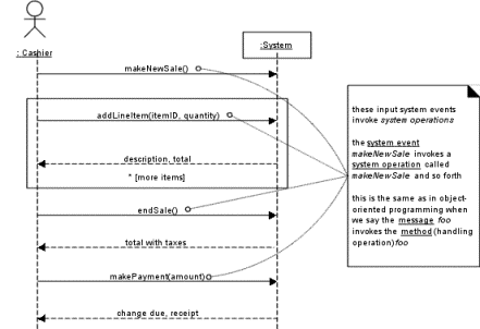
Figure: System operations
handle input system events.
·
Entire set of system
operations, across all use cases, defines the public system interface
o
UML - the system as a
whole can be represented by a class.
Example Contract:
enteritem
Contract C02: enteritem
|
Operation: Cross References: Preconditions: |
enterltem(itemlD:
ItemID, quantity: integer) Use Cases: Process
Sale There is a sale
underway. |
|
Postconditions: |
— A SalesLineltem instance sli was created
(instance creation). — sli was associated with the current Sale
(association formed). — sli.quantity became quantity (attribute
modification). — sli was
associated with a ProductSpecification, based on itemlD match (association
formed). |
Contract Sections
- Template
A description of each
section in a contract is shown in the following schema.
|
Operation: |
Name of operation, and
parameters |
|
Cross References: |
(optional) Use cases this
operation can occur within |
|
Preconditions: |
Noteworthy assumptions about the state of the
system or objects in the Domain Model before execution of the operation.
These will not be tested within the logic of this operation, are assumed to
be true, and are non-trivial assumptions the reader should know were made. |
|
Postconditions: |
The state of objects in
the Domain Model after completion of the operation. Discussed in detail in a
following section. |
Postconditions –
General Discussion
·
Postconditions are
declarations about the Domain Model objects that are true when the operation
has finished
·
Domain Model state
changes include:
·
Instance creation and
deletion.
·
Attribute modification.
·
Associations formed and
broken
·
Advantage of
Postconditions
o
Describes state changes
required of a system operation without having to describe how they are to be achieved.
o
e.g. postconditions:
—
A SalesLineltem instance sli was created (instance creation).
— sli was associated with the current Sale (association formed).
—
sli.quantity became quantity (attribute modification).
—
sli was associated with a ProductSpecification, based on itemlD match
(association formed).
- No comment is made about how a SalesLineltem instance is created,
or associated with a Sale.
·
Express postconditions
in the past tense, to emphasize they are declarations about a state change in
the past.
1. For example:
· (better) A SalesLineltem was created.
· (worse)
Create a SalesLineltem.
Postconditions –enterItem
Postconditions Discussion
Instance Creation and Deletion
After the itemlD and quantity of an item have been entered, the new object SalesLineltem is created:
· A SalesLineltem instance
sli was created (instance creation).
Attribute Modification
After the itemlD and
quantity of an item have been entered by the cashier, the quantity of the SalesLineltem
should have become equal to the quantity
parameter:
· sli.quantity became quantity
(attribute modification).
Associations Formed and Broken
After the itemlD and quantity of an item have been entered by the cashier, the new SalesLineltem should have been related
to its Sale, and related to its ProductSpecification:
·
sli was
associated with the current Sale (association
formed).
·
sli was
associated with a ProductSpecification, based
on itemlD match (association formed).
·
When Are Contracts
Useful ?
Use cases are main
repository of project’s requirements.
Situations where details and
complexity of required state changes are awkward to capture in use cases.
e.g.
airline reservation system and the system operation addNewReservation.
Guidelines for
creating Contracts
1. Identify system operations from the SSDs.
2. Construct a contract for system operations that are complex or
subtle in their results, or which are not clear in the use case
3.
Describe postconditions,
using the following categories:
o instance creation and deletion
o attribute modification
o associations formed and broken
·
State postconditions in
a declarative, passive past tense form to emphasize the declaration of a state
change rather than a design of how it is going to be achieved.
o
e.g.
o (better) A SalesLineltem was created.
o (worse) Create a SalesLineltem.
·
Establish a memory
between existing objects or those newly created by defining the forming of an
association.
o
e.g.,
§
Not enough that new SalesLineltem instance is created when
the enterltem operation occurs.
§
After the operation is
complete, it should be true that the newly created instance was associated with
Sale:
The
SalesLineltem was associated with the
Sale (association formed).
NextGen POS
Example: Contracts
System Operations of Process Sale
Contract COl: inakeNewSale
|
Operation: Cross References: Preconditions: |
MakeNewSale() Use Cases: Process
Sale none |
|
Postconditions: |
— A Sale instance s
was created (instance creation). — s was associated
with the Register (association formed). — Attributes of s
were initialized. |
Contract CO2:
enterltem
|
Operation: Cross References: Preconditions: |
enterltem(itemlD :
ItemID, quantity: integer) Use Cases: Process
Sale There is a sale
underway. |
|
Postconditions: |
— A
SalesLineltem instance sli was created (instance creation). — s/i was associated with the current Sale
(association tormed). — sli.quantity became quantity (attribute
moditication). — sli was associated with a
ProductSpecification, based on itemlD match (association tormed). |
Contract C03:
endSale
|
Operation: Cross References: Preconditions: |
endSale() Use Cases: Process Sale There is a sale underway |
|
Postconditions: |
- Sale.isComplete became
true (attribute modification) |
Contract C04:
makePayment
|
Operation: Cross References: Preconditions: |
makePayment(
amount: Money) Use Cases: Process
Sale There is a sale
underway. |
|
Postconditions: |
— A Payment instance p was created (instance
creation). — p.amount Tendered became amount (attribute
moditication). — p was associated with the current Sale
(association tormed). — The current Sale was associated with the
Store (association tormed); (to add it to the historical log ot completed
sales) |
Contracts,
Operations, and the UML
·
UML formally defines operations:
An
operation is a specification of a transformation or query that an object may be
called to execute
·
A method (in the UML) is an implementation of an operation.
·
UML operation has a:
1. signature (name and parameters)
2. operation
specification - describes the
effects produced by executing the operation (postconditions).
·
Contracts applied to operations
at any level of granularity:
o
e.g.
§
the public operations
(or interface) of a subsystem
§
an abstract class
Operation Contracts
Within the UP
Phases
Inception —— No - too detailed.
Elaboration ——
·
Most contracts written
during elaboration, when most use cases are written.
·
Only write contracts
for the most complex and subtle system operations.
Larman: Chapter 14
FROM REQUIREMENTS TO DESIGN IN THIS ITERATION
Introduction
UP guidelines
–
·
10%
of the requirements investigated in inception
·
slightly
deeper investigation started in first iteration of elaboration.
·
Now
shift emphasis toward designing a solution in terms of collaborating software objects.
Iteratively Do the Right Thing, Do the Thing Right
·
In iterative
development, a transition from primarily a requirements focus to primarily a
design and implementation focus will occur in each iteration.
·
Over course of early
elaboration iterations, requirements discovery will stabilize,
·
By end of elaboration, 80%
of the requirements are reliably defined in detail.
On to Object Design
·
During
object design, a logical solution based on the object-oriented paradigm is
developed.
·
Heart
of solution is the creation of interaction
diagrams, which illustrate how objects collaborate to fulfill the
requirements.
·
After drawing
interaction diagrams, class diagrams are
drawn that summarize the definition of the software classes (and interfaces)
that are to be implemented in software.
·
These
artifacts are part of the Design Model.
·
Interactions diagrams
are the most important for developing a good design
·
Creation of interaction
diagrams requires the application of principles for assigning responsibilities
and the use of design principles and
patterns.
Larman: Chapter 15
INTERACTION DIAGRAM NOTATION
Introduction
·
UML includes interaction diagrams to illustrate how
objects interact via messages.
·
This chapter introduces
notation.
Sequence and Collaboration Diagrams
Interaction
diagram refers to:
· collaboration
diagrams
· sequence
diagrams
·
Collaboration diagrams show object interactions in a graph or network format
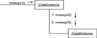
Figure: Collaboration diagram.
·
Sequence diagrams illustrate interactions in a “fence format,” where each new object is
added to the right
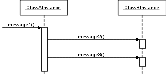
Figure
15.2 Sequence diagram.
·
Strengths and
weaknesses:
o Diagrams for narrow pages - collaboration diagrams
§ Allow vertical expansion for new objects
o Collaboration diagram examples make it harder to
easily see the sequence of messages.
|
Type |
Strengths |
Weaknesses |
|
sequence |
clearly shows sequence or time ordering
of messages simple notation |
forced to extend to the right when add
ing new objects; consumes horizontal space |
|
collaboration |
space economical—flexibility to add new
objects in two dimensions better to illustrate complex branching,
iteration, and concurrent behavior |
difficult to see
sequence of messages more complex notation |
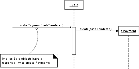
Example Collaboration Diagram: makePayment

Figure: Collaboration diagram.
·
Read the collaboration
diagram shown above as follows:
1. The message makePayment is sent to an instance of a Register. The sender is not identified.
- The Register instance
sends the makePayment message to
a Sale instance.
- The Sale instance creates an instance of a payment
Example
Sequence Diagram: makePayment
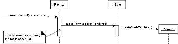
Figure 15.4 Sequence diagram.
·
The sequence diagram
shown above has the same intent as the prior collaboration diagram.
Common Interaction Diagram Notation
UML has adopted a simple and consistent
approach to illustrate instances vs. classifiers
· For any kind
of UML element (class, actor, ...), an instance uses the same graphic symbol as
the type, but the designator string is underlined.
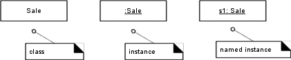
Figure 15.5 Class and instances.
·
To show an instance of
a class in an interaction diagram, the regular class box graphic symbol is
used, but the name is underlined.
o A name can be used to uniquely identify the instance.
o If none is used, a “:“ precedes the class
name.
·
UML has a standard
syntax for message expressions:
return := message(parameter : parameterType) : returnType
- Type information may be excluded if obvious or unimportant. For
example:
spec
:= getProductSpect(id)
spec
:= getProductSpect(id:ItemID)
spec
:= getProductSpect(id:Ite.mID) : ProductSpecification
Basic Collaboration Diagram Notation
·
Links
- A link is a connection
path between two objects;
o it indicates that some form of navigation and
visibility between the objects is possible (see Figure 15.6).
o More formally, a link is an instance of an
association.
e.g., there is a link from
a Register to a Sale, along which messages may flow, such as the makePayment message.
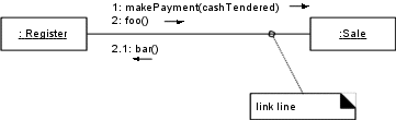
Figure:
Link lines.
o
Multiple
messages can flow along the same single link in both directions.
·
Messages
o Each message between objects is represented with a
message expression and small arrow indicating the direction of the message.
o Many messages may flow along this link
o A sequence number is added to show the sequential
order of messages in the current thread of control.
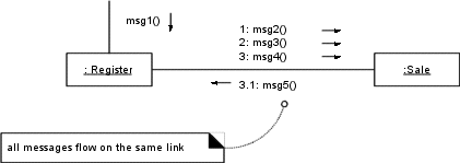
Figure: Messages.
·
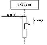
Messages to “self” or “this”
o A message can be sent from an object to itself
o Shown by a link to itself, with messages flowing
along the link.
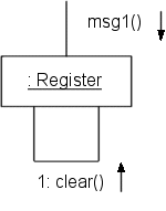
Figure : Messages to
“this.”
·
Creation of Instances
o
Any message can be used
to create an instance
o In UML - use a message named create for this purpose.
o If another (less obvious) message name is used, the
message may be annotated with a special feature called a UML stereotype, like
so: «create».
o The create message
may include parameters, indicating the passing of initial values.
o UML property [new]
may optionally be added to the instance box to highlight the creation.
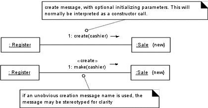
Figure : Instance creation.
·
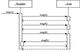
Message Number Sequencthg
o The order of messages is illustrated with sequence numbers
o The numbering scheme is:
1. The first message is not numbered.
msg1( ) is
unnumbered.
2. The order and nesting of subsequent messages is shown
with a legal numbering scheme
·
Nested messages have a
number appended to them.
·
Nesting is denoted by
prepending the incoming message number to the outgoing message number.
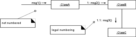
Figure :Sequence
numbering.
·
Conditional Messages
o A conditional message is shown by following a
sequence number with a conditional clause in square brackets, similar to an
iteration clause.
o The message is only sent if the clause evaluates to true.
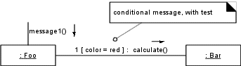
Figure : Conditional
message.
·
Mutually Exclusive Conditional Paths
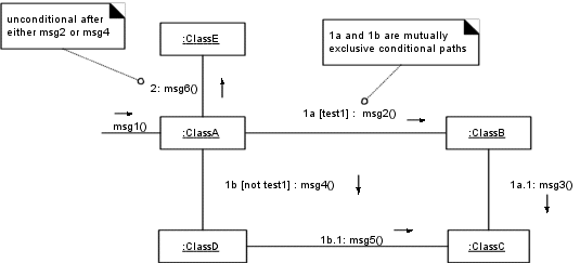
Figure :Mutually
exclusive messages
o Must modify the sequence expressions with a conditional
path letter.
o The first letter used is a by convention.
o Figure states that either 1a or 1b could execute
after msg1.
o Both are sequence number 1 since either could be the
first internal message.
o Subsequent nested messages are still consistently
prepended with their outer message sequence.
1b.1 is
nested message within 1b.
·
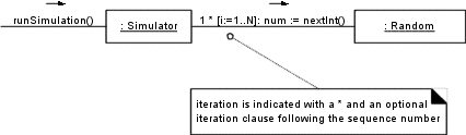
Iteration or Looping
·
If the details of the
iteration clause are not important to the modeler, a simple ‘*’ can be used.
·
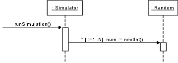
Iteration Over a Collection (Multiobject)
o
Common algorithm - iterate
over all members of a collection (e.g. a list or map), sending a message to
each.
o
Some kind of iterator
object is used
o
UML - term multiobject - used to denote a set of
instances — a collection.
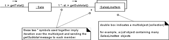
Figure : Iteration over a
multiobject.
o
The “*“ multiplicity
marker is used at the end of the link to indicate that the message is being
sent to each element of the
·
Messages to a Class Object
o
Messages may be sent to
a class itself to invoke class or static
methods.
o
A message is shown to a class
box whose name is not underlined, indicating the message is being sent
to a class rather than an instance
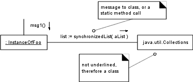
Figure: Messages to a
class object (static method invocation)
Basic Sequence Diagram
Notation
Links
o
Unlike collaboration
diagrams, sequence diagrams do not show links.
Messages
o
Each message between
objects is represented with a message expression on an arrowed line between the
objects
o
Time ordering is organized
from top to bottom.
Figure: Messages and focus of control
with activation boxes.
o
Sequence diagrams may show
the focus of control (that is, in a regular blocking call, the operation is on
the call stack) using an activation box.
o
The box is optional,
but commonly used by UML practitioners.
Illustrating Returns
o
A sequence diagram may show the return from a
message as a dashed open-arrowed line at the end of an activation box
o Many practitioners exclude them.
o Some annotate the return line to describe what is
being returned (if anything) from the message.
Messages to “self” or “this”
o
Use nested activation box.
Creation of Instances
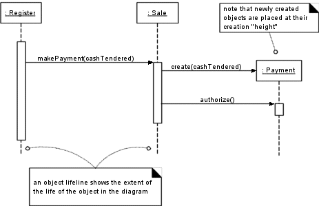
Figure
: Instance creation and object lifelines.
·
object lifelines
—vertical dashed lines underneath the objects
·
Indicate the extent of
the life of the object in the diagram.
·
In some circumstances
it is desirable to show explicit destruction of an object
·
UML lifeline notation
provides a way to express this destruction
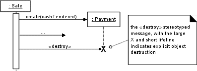
Figure: Object Destruction
Conditional Messages
A condition message is shown in Figure
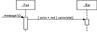
Figure : A conditional
message.
Mutually Exclusive Conditional Messages
Notation is a angled message line
emerging from a common point
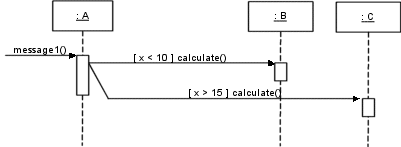
Figure :Mutually exclusive conditional
messages.
Iteration for a Single Message
Iteration notation for one message is
shown.
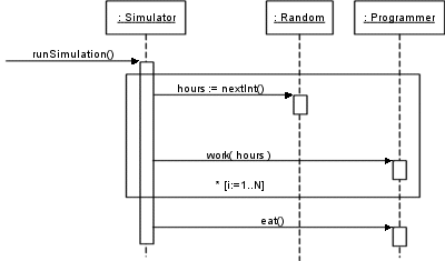
Iteration of a Series of Messages
Notation to indicate iteration around a
series of messages is shown
Iteration Over a Collection (Multiobject)
In sequence diagrams, iteration over a
collection is shown
·
A ‘*‘ multiplicity marker at the end of the role (next to
the multiobject) to indicate sending a message to each element rather than
repeatedly to the collection itself.
Messages to Class Objects
·
Class or static method
calls are shown by not underlining the name of the classifier, which
signifies a class object rather than an instance
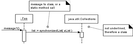
Figure: Invoking class or static methods.
Larman: Chapter 16
GRASP: DESIGNING OBJECTS WITH RESPONSIBILITIES
Introduction
·
The GRASP patterns are
a learning aid to help understand essential object design, and apply design
reasoning in a methodical, rational, explainable way
·
This approach is based
on patterns of assigning
responsibilities.
Responsibilities and Methods
·
UML defines a responsibility as “a contract or obligation
of a classifier”
·
Responsibilities are
related to the obligations of an object in terms of its behavior.
Two types:
· knowing
· doing
·
Doing responsibilities
of an object include:
- doing something itself, such as creating an object or doing a
calculation
- initiating action in other objects
- controlling and coordinating activities in other objects
·
Knowing responsibilities
of an object include:
- knowing about private encapsulated data
- knowing about related objects
- knowing about things it can derive or calculate
·
Responsibilities are
assigned to classes of objects during object design.
e.g. “
·
“a Sale is responsible for creating SalesLineltems” (a doing)
·
“a Sale is responsible for knowing its total” (a knowing).
·
Relevant
responsibilities related to “knowing” are often inferable from the domain
model, because of the attributes and associations it illustrates.
·
Responsibilities are
implemented using methods that either act alone or collaborate with other
methods and objects.
Responsibilities and Interaction
Diagrams
·
Interaction diagrams
show choices in assigning responsibilities to objects
Figure
: Responsibilities and methods are related.
·
Figure shows that Sale objects have been given a
responsibility to create Payments, which
is invoked with a makePayment message
and handled with a corresponding makePayment
method.
·
Fulfillment of this
responsibility requires collaboration to create the SalesLineltem object and invoke its constructor.
Patterns
·
Patterns are
a collection of general principles and idiomatic solutions that guide programmers
in the creation of software.
·
Sample pattern:
|
Pattern Name: |
Information Expert |
|
Solution: |
Assign a responsibility to the class that has the
information needed to fulfill it. |
|
Problem It Solves: |
What is a basic principle by which to assign
responsibilities to objects? |
·
Object technology - a pattern is a named description of a
problem and solution that can be applied to new contexts
o it provides advice in how to apply it in varying
circumstances, and considers the forces and trade-offs.’
o Many patterns provide guidance for how
responsibilities should be assigned to objects, given a specific category of
problem.
·
All patterns have
suggestive names.
Advantages:
· Supports
chunking and incorporating that concept into understanding and memory.
· Facilitates
communication.
·
GRASP patterns have
concise names such as Information Expert,
Creator, Protected Variations.
GRASP: Patterns
of General Principles in Assigning Responsibilities
Question: What are the GRASP
patterns?
Answer: They describe fundamental principles of object design
and responsibility assignment, expressed as patterns.
·
GRASP is an acronym
that stands for General Responsibility Assignment Software Patterns.
·
First five GRASP
patterns:
· Information
Expert
· Creator
· High Cohesion
· Low Coupling
· Controller
The UML Class Diagram Notation
·
A UML class box illustrates
software classes by showing three compartments
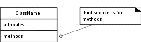
Figure :
Software classes illustrate method names.
Information Expert (or Expert)
Solution Assign a
responsibility to the information expert — the class that has the information necessary to fulfill the
responsibility.
Problem What is a general principle of assigning
responsibilities to objects?
Example In the NextGEN POS application, some class needs to
know the grand total of a sale.
Start assigning
responsibilities by clearly stating the responsibility.
Ask:
Who should be responsible for knowing the grand total of a sale?
·
By Information Expert, look for that class of objects that has the
information needed to determine the total.
Key question: Do we look in the Domain Model or the Design Model
to analyze the classes that have the information needed?
·
The Domain Model
illustrates conceptual classes of the real-world domain
·
The Design Model illustrates
software classes.
Answer:
1. If there are relevant classes in the Design
Model, look there first.
2. Else, look in the Domain Model, and attempt to
use (or expand) its representations to inspire the creation of corresponding
design classes.
·
e.g.
o assume we have begun design work and there is no or a
minimal Design Model.
o Therefore, look to the Domain Model for information
experts;
§ perhaps the real-world Sale is one.
o Then add a software class to the Design Model called Sale, and give it the responsibility of
knowing its total, expressed with the method named getTotal.
·
This approach supports low representational gap in which the
software design of objects appeals to our concepts of how the real domain is
organized.
·
To examine this case in
detail, consider the partial Domain Model in Figure
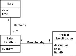
Figure : Associations of Sale.
·
What information is
needed to determine the grand total?
·
It is necessary to know
about all the SalesLineltem instances
of a sale and the sum of their subtotals.
·
A Sale instance contains these
·
therefore, by the
guideline of Information Expert, Sale is
a suitable class of object for this responsibility;
·
It is an information expert for the work.
·
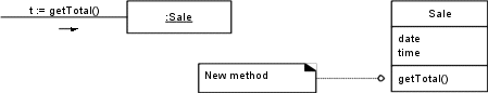
Interaction diagram
creation raises questions of responsibility.
e.g.
·
we are starting to work
through the drawing of diagrams in order to assign responsibilities to objects.
·
A partial interaction
diagram and class diagram
·
What information is
needed to determine the line item subtotal?
o SalesLineltem.
quantity and ProductSpecification.price
§ SalesLineltem
knows its quantity and its
associated ProductSpecification;
§ Ttherefore, by Expert, SalesLineltem should determine the subtotal; it is the information expert.
In terms of an interaction diagram, this
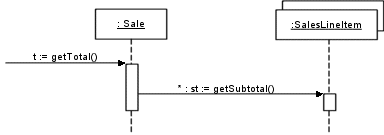
means that the Sale needs to send get-Subtotal messages to each of the SalesLineltems and sum the results;
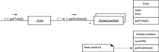
Figure
: Calculating the Sale total.
·
To fulfill the responsibility
of knowing and answering its subtotal, a SalesLineltem
needs to know the product price.
·
The ProductSpecification is an information
expert on answering its price; therefore, a message must be sent to it asking
for its price.
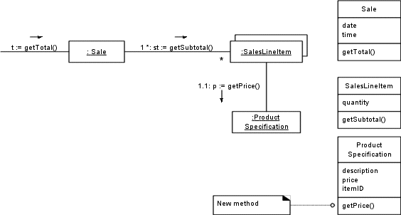
Figure: Calculating the Sale
total
·
So, to fulfill the
responsibility of knowing and answering the sale’s total, three responsibilities
were assigned to three design classes of objects as follows.
|
Design Class |
Responsibility |
|
Sale |
knows sale total |
|
SalesLineltem |
knows line item
subtotal |
|
ProductSpecification |
knows product price |
The context in which these
responsibilities were considered and decided upon was while drawing an interaction
diagram. The method section of a class diagram can then summarize the methods.
The principle by which each
responsibility was assigned was Information Expert—placing it with the object
that had the information needed to fulfill it.
·
Information Expert is
frequently used in the assignment of responsibilities
o
Basic guiding principle
used continuously in object design.
·
Fulfillment of a
responsibility often requires information that is spread across different
classes of objects.
o
Many “partial”
information experts who will collaborate in the task.
o
For example, the sales
total problem ultimately required the collaboration of three classes of
objects.
·
Whenever information is
spread across different objects, they will need to interact via messages to
share the work.
Contraindications
·
Situations where a
solution suggested by Expert is undesirable, usually because of problems in
coupling and cohesion
o
e.g. who should be
responsible for saving a Sale in a
database?
o
Much of the information
to be saved is in the Sale object,
and thus by Expert an argument could be made to put the responsibility in the Sale class.
o
Logical extension of
this decision is that each class has its own services to save itself in a
database.
o
Leads to problems in
cohesion, coupling, and duplication.
§
the Sale class must now contain logic
related to database handling
§
The class is no longer
focused on just the pure application logic of “being a sale;” it now has other
kinds of responsibilities, which lowers its cohesion.
§
The class must be
coupled to the technical database services of another subsystem, rather than
just being coupled to other objects in the domain layer of software objects,
which raises its coupling.
§
Likely that similar
database logic would be duplicated in many persistent classes.