CS616 – Software
Engineering II
|
Lecture 7
|
Larman – Chapter 17 |
DESIGN MODEL: USE-CASE REALIZATIONS WITH GRASP PATTERNS
|
|
Objectives |
|
· |
Design use-case realizations. |
|
· |
Apply the GRASP patterns to assign
responsibilities to classes. |
|
· |
Use the UML interaction diagram
notation to illustrate the design of objects. |
Use-Case Realizations
·
A use-case realization
describes how a particular use case is realized within the design model, in
terms of collaborating objects
·
Designer describes the
design of one or more scenarios of a
use-case: each is called a use-case realization.
·
UML interaction
diagrams illustrate use-case realizations.
· A use case
suggests the system events that are explicitly shown in system sequence diagrams.
· Details of the effect of system events in terms of changes to domain objects may be described in system operation contracts.
· System
events represent messages that initiate interaction diagrams, which illustrate
how objects interact to fulfill the required tasks—the use case realization.
· Interaction diagrams involve message interaction between software objects whose names are sometimes inspired by the names of conceptual classes in the Domain Model, plus other classes of objects.
Interaction Diagrams and Use-Case Realizations
·
Current iteration
considers scenarios and system events such as:
o
Process Sale: makeNewSale, enterltem, endSale,
makePayment
·
For collaboration
diagrams illustration of the use-case realizations,
o
different collaboration
diagram required for each system event message.
Collaboration diagrams and
system event message handling.
·
For sequence diagrams
use - fit all system event messages on the same diagram
Figure
·
If sequence diagram is too complex or long - use
a sequence diagram for each system event message
Multiple sequence diagrams
and system event message handling.
Contracts and Use-Case Realizations
·
Possible to design
use-case realizations directly from use case text.
·
For some system
operations, contracts may have been written that add greater detail or
specificity
·
For example:
Contract C02: enteritem
|
Operation: Cross References: Preconditions: |
enterltem(itemlD: ItemiD,
quantity: integer) Use Cases: Process Sale There is a sale underway. |
|
Postconditions: |
— A SalesLineltem instance sli was
created (instance creation). — … |
·
For each contract work
through the postcondition state changes and design message interactions to
satisfy the requirements.
·
For example
o
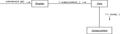
given this partial enterltem system operation, a partial interaction diagram is shown
below that satisfies the state change of SalesLineltem
instance creation.
Partial interaction
diagram.
The Domin Model and Use-Case Realizations
·
Some software objects
that interact via messages in the interaction diagrams are inspired from the
Domain Model
o
e.g. Sale conceptual class and Sale design class
·
Choice of appropriate
responsibility placement using the GRASP patterns relies, in part, upon
information in the Domain Model.
Conceptual vs. Design Classes
·
UP Domain Model does
not illustrate software classes, but may be used to inspire the presence and
names of some software classes in the Design Model.
·
During interaction
diagramming or programming, Domain Model used to name design classes
·
Creates a design with
lower representational gap between the software design and our concepts of the
real domain to which the software is related
Figure :Lowering
representational gap with design classes named from conceptual classes.
Use-Case Realizations for the NextGen Iteration
Object Design: makeNewSale
·
makeNewSale system
operation occurs when a cashier starts a new sale, after a customer has arrived
with things to buy
Contract COl: makeNewSale
|
Operation: Cross References: Preconditions: |
makeNewSale() Use Cases: Process Sale None |
|
Postconditions: |
— A Sale instance s
was created (instance creation). — s was associated
with the Register (association formed). — Attributes of s were
initialized. |
Choosing the Controller Class
·
Choose the controller
for the system operation message enterltem.
·
By the Controller
pattern, here are some choices:
|
represents the overall
“system,” device, or subsystem |
Register, POSSystem |
|
represents a receiver or handler
of all system events of a use case scenario |
ProcessSaleHandler, ProcessSaleSession |
·
Choosing a facade
controller like Register is
satisfactory if there are only a few system operations and the facade controller
is not taking on too many responsibilities (in other words, if it is becoming
incohesive).
·
Choosing a use-case
controller is suitable when there are many system operations and we wish to
distribute responsibilities in order to keep each controller class lightweight
and focused (in other words, cohesive).
·
In this case, Register will suffice, since there are
only a few system operations.
·
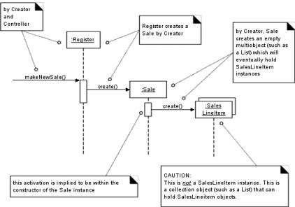
The interaction diagram
shown below begins by sending the makeNewSale
message to a Register software
object.
Figure: Applying the GRASP
Controller pattern.
Creating a New Sale
·
A software Sale object must be created
·
GRASP Creator pattern
suggests assigning the responsibility for creation to a class that aggregates, contains,
or records the object to be created.
·
Register may
be thought of as recording a Sale
·
Register is
a reasonable candidate for creating a Sale.
·
By having
the Register create the Sale, the Register can easily be associated with it over time,
o
During future
operations within the session, the Register
will have a reference to the current Sale
instance.
·
When the Sale is created
o
it must create an empty
collection (container) to record all
future SalesLineItem instances that
will be added.
o
This collection will be
contained within and maintained by the Sale
instance,
·
Therefore:
o
the Register creates the Sale
o
the Sale creates an empty collection,
represented by a multiobject in the interaction diagram.
Object Design: enterltem
o
enterltem system
operation occurs when a cashier enters the itemlD
and the quantity of something to be purchased.
Contract C02: enterltem
|
Operation: Cross References: Preconditions: |
enterltem(itemlD: itemiD, quantity: integer) Use Cases: Process Sale There is an
underway sale. |
|
Postconditions: |
— A SalesLineitem
instance sli was created (instance creation). — sli was associated with
the current Sale (association formed). — sli quantity became quantity
(attribute modification). — sli
was associated with a ProductSpecification, based on itemlD match
(association formed). |
Choosing the Controller Class
·
Handle the
responsibility for the system operation message enterltem.
·
Based on the Controller
pattern - continue to use Register as a controller.
Display Item Description and Price?
·
Model-View Separation design principle - not the responsibility of non-GUI
objects (such as a Register or Sale) to do output tasks.
·
Although the use case
states that the description and price are displayed after this operation, the
design will be ignored at this time.
Creating a New SalesLineltem
·
enterltem contract
postconditions indicate the creation, initialization, and association of a SalesLineltem.
·
Domain Model reveals
that a Sale contains SalesLineItem objects.
·
Software Sale may contain software SalesLineltem.
·
Hence, by Creator, a
software Sale is an appropriate
candidate to create a SalesLineltem.
·
Sale is
associated with the newly created SalesLineItem
by storing the new instance in its collection of line items.
·
Postconditions indicate
that the new SalesLineItem needs a
quantity, when created:
o
Therefore
§
the Register must pass it along to the Sale,
§
Sale must
pass it along as a parameter in the create
message
·
By Creator:
o
makeLineItem message is sent to a Sale for
it to create a SalesLineltem.
o
Sale creates
a SalesLineltem, and then stores the
new instance in its permanent collection.
·
Parameters to the makeLineItem message include the quantity, so SalesLineItem can record it, and likewise the ProductSpecification which matches the itemlD.
Finding a ProductSpecification
·
SalesLineItem needs to be associated with the ProductSpecification
that matches the incoming itemlD.
·
Must retrieve a ProductSpecification, based on an itemlD match.
- Find Responsibilities for the lookup:
o Start assigning responsibilities by clearly stating
the responsibility.
o
Answer the Question:
Who
should be responsible for knowing a ProductSpecification,
based on an itemlD match?
·
Typically, the Expert
pattern is the principal pattern to apply.
o
Domain Model reveals
that the ProductCatalog logically
contains all the ProductSpecifications.
o
Design software classes
with similar organization: a software ProductCatalog
will contain software ProductSpecifications.
o
By Information Expert -
ProductCatalog is a good candidate
for this lookup responsibility since it knows all the ProductSpecification objects.
o
Implemented with a
method called getSpecification.’
Visibility to a ProductCatalog
o
Who should send the
getSpecification message to the ProductCatalog to ask for a
ProductSpecification?
o
Reasonable to assume:
o
Register and
ProductCatalog instance were created during the initial Start Up use case
o
There is a permanent
connection from the Register object to the ProductCatalog object.
o
Possible for the Register to send the getSpecification message to the ProductCatalog.
o
Another concept in
object design: visibility.
Visibility is the ability of one object to “see” or have a reference to another object.
o
For an object to send a
message to another object it must have visibility to it.
o
Assume that the Register has a permanent connection — or
reference— to the ProductCatalog
o
It has visibility to
it, and can send it messages such as getSpecification
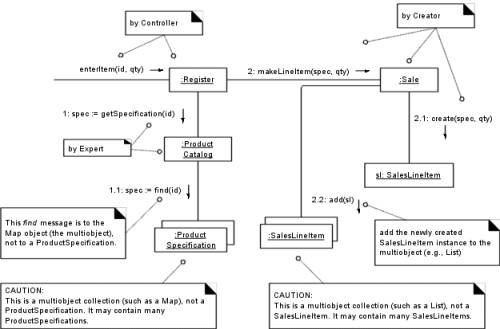
Messages to Multiobjects
o
Interpretation of a
message sent to a multiobject in UML is that it is a message to the collection
object itself, rather than an implicit broadcast to the collection’s members.
o
For example, in the enterltem interaction diagram:
o
The find message sent to the ProductSpecification multiobject is a
message being sent once to the collection data structure represented by the
multiobject
§
The
language-independent and generic find message
will be translated for a specific language and library
o
The add message sent to the SalesLineItem multiobject is to add an
element to the collection data structure represented by the multiobject
Connecting the UI Layer
to the Domain Layer
§
Applications are
organized into logical layers that separate the major concerns of the
application
§
e.g. the UI layer (for
UI concerns) and “domain” layer (for domain logic concerns).
§
Common designs by which
objects in the UI layer obtain visibility to objects in the domain layer
include the following:
o
An initializing routine
(for example, a Java main method)
creates both a UI and a domain object, and passes the domain object to the UI.
o
A UI object retrieves
the domain object from a well-known source, such as a factory object that is
responsible for creating domain objects.
§
Sample code is an
example of the first approach:
public class Main
{
public static void main(
String[] args)
{
Store store = new
Store~
Register register = store.getRegister~
ProcessSalejFrame frame = new
ProcessSalejFrame( register );
…
}
}
o
Once the UI object has
a connection to the Register instance
(the facade controller in this design), it can forward system event messages to
it, such as the enterltem and endSale message
Figure Connecting the UI and
domain layers.
o
For the enterltem message, the window needs to
show the running total after each entry.
o
There are several
design solutions:
o
Add a getTotal method to the Register. The UI sends the getTotal message to the Register, which forwards it to the Sale.
§
Possible advantage of
maintaining lower coupling from the UI to the domain layer — the UI only knows
of the Register object. But it starts
to expand the interface of the Register object, making it less cohesive.
o
A UI asks for a reference
to the current Sale object, and then
when it needs the total (or any other information related to the sale), it
directly sends messages to the Sale.
§
This design increases
the coupling from the UI to the domain layer.
Interface and Domain Layer Responsibilities
§
The UI layer should not
have any domain logic responsibilities. It should only be responsible for user
interface tasks, such as updating widgets.
§
The UI layer should forward
requests for all domain-oriented tasks on to the domain layer, which is
responsible for handling them.
Figure: design follows the
second approach.
In these diagrams the Java
window (ProcessSaleJFrame), which is
part of the UI layer, is not responsible for handling the logic of the
application.
Use-Case
Realizations Within the UP
Use-case realizations are
part of the UP Design Model.
|
Discipline |
Artifact |
Incep. |
Elab. |
Const. |
Trans. |
|
Business Modeling |
Domain Model |
|
s |
|
|
|
Requirements |
IJse-Case Model (SSDs) |
s |
r |
|
|
|
|
Vision |
s |
r |
|
|
|
|
Supplementary Specification |
s |
r |
|
|
|
|
Glossary |
s |
r |
|
|
|
Design |
Design Model |
|
s |
r |
|
|
|
SW Architecture Document |
|
s |
|
|
|
|
Data Model |
|
s |
r |
|
|
Implementation |
Implementation Model |
|
s |
r |
r |
|
Project Management |
SW Development Plan |
s |
r |
r |
r |
|
Testing |
Test Model |
|
s |
r |
|
|
Environment |
Development Case |
s |
r |
|
|
Table: Sample UP artifacts
and timing. s - start; r - refine
Phases
Inception—The
Design Model and use-case
realizations will not usually be started until elaboration because it involves detailed
design decisions which are premature during inception.
Elaboration—During
this phase, use-case realizations
may be created for the most architecturally significant or risky scenarios of
the design. However, IJML diagramming will not be done for every scenario, and
not necessarily in complete and fine-grained detail. The idea is to do
interaction diagrams for the key use-case realizations that benefit from some
forethought and exploration of alternatives, focusing on the major design
decisions.
Construction—Use-case realizations are created for remaining
design problems.
Larman: Chapter 18 |
DESIGN MODEL: DETERMINING VISIBILITY
|
|
Objectives |
|
· |
Identify four kinds of
visibility. |
|
· |
Design to establish
visibility |
|
· |
Illustrate kinds of
visibility in the UML notation. |
Introduction
Visibility is the ability of
one object to see or have reference to another.
Visibility Between Objects
§
Designs created for the
system events (enterltem, and so on) illustrate
messages between objects.
§
For a sender object to
send a message to a receiver object, the sender must be visible to the receiver
— the sender must have some kind of reference or pointer to the receiver
object.
§
For example
o
the getSpecification message sent from a Register to a ProductCatalog implies that the ProductCatalog
instance is visible to the Register instance,
as shown below
§
When creating a design
of interacting objects, it is necessary to ensure that the required visibility
is present to support message interaction.
Visibility
§
Visibility
is the ability of an object to “see”
or have a reference to another object.
§
Related to the issue of
scope:
Is one resource (such as an instance) within the scope of another?
§
Four ways that
visibility can be achieved from object A to
object B:
o
Attribute
visibility — B is an attribute of A.
o
Parameter
visibility — B is a parameter of a
method of A.
o
Local
visibility — B is a (non-parameter)
local object in a method of A.
o
Global
visibility — B is in some way globally visible
§
Motivation:
For an object A to send a message to an object B, B must be visible to A.
§
For example:
o
to create an
interaction diagram in which a message is sent from a Register instance to a ProductCatalog
instance, the Register must have
visibility to the ProductCatalog.
o
A typical visibility
solution is that a reference to the ProductCatalog
instance is maintained as an attribute of the Register.
Attribute visibility from A to B exists when B is an attribute
of A.
o
Relatively permanent visibility because it persists as long as A
and B exist.
o
Common form of
visibility in object-oriented systems.
e.g. in a Java class
definition for Register, a Register instance may have attribute
visibility to a ProductCatalog, since
it is an attribute (Java instance variable) of the Register.
public class Register
{
…
private ProductCatalog catalog;
…
}
§
This visibility is
required because in the enterltem diagram
below, a Register needs to send the getSpecification message to a ProductCatalog:
Parameter Visibility
§
Parameter
visibility from A to B exists when B
is passed as a parameter to a method of A.
§
Temporary visibility -
because it persists only within the scope of the method.
§
After attribute
visibility, it is the second most common form of visibility in object-oriented
systems.
§
e.g. when the makeLineltem message is sent to a Sale instance, a ProductSpecification instance is passed as a parameter. Within the
scope of the makeLineltem method, the
Sale has parameter visibility to a ProductSpecification
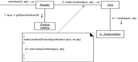
Figure :Parameter visibility
§
Common to transform
parameter visibility into attribute visibility
§
For example:
o
when the Sale creates a new SalesLineltem, it passes a ProductSpecification
to its initializing method.
o
Within the initializing
method, the parameter is assigned to an attribute, thus establishing attribute
visibility
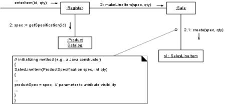
Figure Parameter to
attribute visibility.
Local Visibility
§
Local
visibility from A to B exists when B
is declared as a local object within a method of A.
§
Temporary visibility
because it persists only within the scope of the method.
§
After parameter
visibility, it is the third most common form of visibility in object-oriented
systems.
§
Two common means by which
local visibility is achieved are:
o
Create a new local
instance and assign it to a local variable.
o
Assign the returning
object from a method invocation to a local variable.
§
Common to transform
locally declared visibility into attribute visibility.
§
Example of the second
variation (assigning the returning object to a local variable) can be found in
the enterltem method of class Register
Figure Local visibility.
Global
Visibility
§
Global visibility from A to B exists when B is global to A.
§
Permanent visibility
because it persists as long as A and B exist.
§
It is the least common
form of visibility in object-oriented systems.
§
One way to achieve
global visibility is to assign an instance to a global variable, which is
possible in some languages
Illustrating Visibility in the UML
- The UML includes notation to show the kind of
visibility in a collaboration diagram
- These adornments are optional and not normally
called for; they are useful when clarification is needed.
Larman: Chapter 19 |
DESIGN MODEL: CREATING DESIGN CLASS DIAGRAMS
|
|
Objectives |
|
· |
Create design class diagrams (DCDs). |
|
· |
Identify the classes, methods, and
associations to show in a DCD. |
Introduction
·
Interaction diagrams
for use-case realizations completed
·
Can identify the
specification for the software classes (and interfaces) that participate in the
software solution, and annotate them with design details, such as methods.
·
UML notation for
showing design details in class diagrams is explored to create DCDs.
When to Create DCDs
·
DCDs and interaction diagrams created in
parallel.
·
DCDs may be used as an
alternative to CRC cards in order to record responsibilities and collaborators.
Example DCD
·
DCD below illustrates a
partial software definition of the Register and Sale classes.
Figure Sample design class
diagram.
·
The diagram is extended
to illustrate the:
o
methods of each class
o
attribute type
information
o
attribute visibility
and navigation between objects.
DOD and UP Terminology
·
A design class diagram (DCD) illustrates the specifications for software classes and interfaces in an application.
·
Typical information
includes:
· classes,
associations and attributes
· interfaces,
with their operations and constants
· methods
· attribute
type information
· navigability
· dependencies
·
Design classes in the
DCDs show definitions for software classes rather than real-world concepts.
Domain Model vs. Design Model Classes
Domain Model
·
A Sale does not represent a software definition
·
It is an abstraction of
a real-world concept
DCDs
- DCDs express the definition of classes as
software components.
- In these diagrams, a Sale represents a software class
Figure : Domain model vs.
Design Model classes.
Creating a NextGen POS DCD
Identify Software Classes and Illustrate Them
·
First step in creation of DCDs is to identify those classes
that participate in the software solution.
o
Find them by scanning
all the interaction diagrams and listing the classes mentioned.
o For POS -
|
Register |
Sale |
|
ProductCatalog |
ProductSpecification |
|
Store |
SalesLineltem |
|
Payment |
|
·
Second step - draw class diagrams for these classes and include
the attributes previously identified in the Domain Model that are also used in
the design (see Figure 19.3).
Figure
: Software classes in the application.
·
Note: some concepts in
the Domain Model, such as Cashier, are
not present in the design.
o
no need now — include
later
Add Method Names
·
Identify methods of
each class by analyzing the interaction diagrams.
o
For example, if the
message makeLineltem is sent to an
instance of class Sale, then class Sale must define a makeLineltem method
Figure : Method names from
interaction diagrams.
·
Inspection of all the
interaction diagrams for the POS application yields the allocation of methods
shown in Figure 19.5.
Figure : Methods in the
application.
Method Name Issues
The following special issues
must be considered with respect to method names:
· interpretation of the create
message
· depiction of accessing methods
· interpretation of messages to multiobjects
· language-dependent syntax
Method Names—Multiobjects
·
A message to a
multiobject is interpreted as a message to the container/collection object
itself
o
For example, the find message to the multiobject is meant
be interpreted as a message to the container/collection object
Figure : Message to a
multiobject.
o
The find method is not part of the ProductSpecification class;
o
It is part of the
multiobject’s interface.
o
It is incorrect to add find as a method to the ProductSpecification class.
Adding More Type Information
·
Types of the
attributes, method parameters, and method return values may all optionally be
shown.
·
Whether to show this
information or not should be considered in the following context:
Is it necessary to show all the parameters and their type information? It depends on how obvious the information is to the intended audience.
Figure : Adding type
information.
Adding Associations and Navigability
·
Each end of an
association is called a role
·
For DCDs - the role may
be decorated with a navigability arrow.
·
Navigability is a property of the role that indicates that it is
possible to navigate uni-directionally across the association from objects of
the source to target class.
·
Navigability implies
visibility—usually attribute visibility
Figure : Showing
navigability, or attribute visibility.
·
Usual interpretation -
attribute visibility from the source to target class.
·
During implementation -
translated as the source class having an attribute that refers to an instance
of the target class.
o
For example, the Register class will define an attribute
that references a Sale instance.
·
Associations are chosen
by a need-to-know criterion:
What associations are required to satisfy the visibility and ongoing memory needs indicated by the interaction diagrams?
·
Required visibility and
associations between classes are indicated by the interaction diagrams.
o
Common situations
suggesting a need to define an association with a navigability adornment from A
to B:
§
A sends a message to B.
§
A creates an instance
B.
§
A needs to maintain a
connection to B.
o
For example, from interaction
diagram below:
§
Store should
probably have an ongoing connection to the Register
and ProductCatalog instances that
it created
§
ProductCatalog needs an ongoing connection to the collection of ProductSpecifications it created.
§
These implied
connections will therefore be present as associations in the class diagram.
·
Based on the above
criterion for associations and navigability, analysis of all the interaction
diagrams generated for the NextGen POS application will yield a class diagram
Figure : Associations with
navigability adornments.
Adding Dependency Relationships
·
UML includes a general dependency relationship, which
indicates that one element (of any kind, including classes, use cases, and so
on) has knowledge of another element.
o
Illustrated with a
dashed arrow line
Notation for Member Details
UML provides a notation to
describe features of class and interface members, such as visibility, initial
values, and so on.
Figure : Some UML class
diagram member notation details.
Visibility Defaults in the UML?
Common convention -
attributes are private and methods public, unless otherwise noted.
DCDs Within the UP
·
DCDs are part of the
use-case realizations and thus members of the UP Design Model.
|
Discipline |
Artifact Iteration-> |
Incep. |
Elab. |
Const. |
Trans. |
|
Business Modeling |
Domain Model |
|
s |
|
|
|
Requirements |
Use-Case Model (SSDs) |
s |
r |
|
|
|
|
Vision |
s |
r |
|
|
|
|
Supplementary Specifications |
s |
r |
|
|
|
|
Glossary |
s |
r |
|
|
|
Design |
Design Model |
|
s |
r |
|
|
|
SW Architecture Document |
|
s |
|
|
|
|
Data Model |
|
s |
r |
|
|
Implementation |
Implementation Model |
|
s |
r |
r |
|
Project Management |
SW Development Plan |
s |
r |
r |
r |
|
Testing |
Test Model |
|
s |
r |
|
|
Environment |
Development Case |
s |
r |
|
|
Table : Sample UP artifacts
and timing. s - start; r - refine
Phases
Inception—The Desigu Model and DCDs will not usually be
started until elaboration because it involves detailed design decisions, which
are premature during inception.
Elaboration—During this phase, DCDs will accompany the use-case realization interaction
diagrams; they may be created for the most architecturally significant classes
of the design.
Note that CASE tools can
reverse-engineer (generate) DCDs from source code. It is recommended to
generate DCDs regularly from the source code, to visualize the static structure
of the system.
Construction—DCDs will continue to be generated from the source
code as an aid in visualizing the static structure of the system.
Larman: Chapter 20
|
IMPLEMENTATION MODEL: MAPPING DESIGNS TO CODE
Objectives |
|
· Map design artifacts to code in an object-oriented
language. |
Introduction
·
Interaction diagrams
and DCDs done for current iteration of the NextGen
·
Sufficient detail to
generate code for the domain layer of objects.
·
Interaction diagrams
and DCDs used as input to code generation process.
·
UP defines the
Implementation Model - artifacts such as the source code, database definitions,
etc.
Programming and the Development Process
- Strength of OOA/D and 00 programming — when used
with the UP— is that they provide an end-to-end roadmap from requirements
through to code.
- Various artifacts feed into later artifacts in a
traceable and useful manner, ultimately culminating in a running
application.
Figure : Implementation in
an iteration influences later design.
·
Early activity within
an iteration is to synchronize the design diagrams
o
earlier diagrams of
iteration N will not match the final code of iteration N
o
they need to be
synchronized before being extended with new design results.
Mapping Designs to Code
·
Implementation in an
object-oriented programming language requires writing source code for:
o
class and interface
definitions
o
method definitions
Creating Class Definitions from DCDs
·
DCDs depict the class
or interface name, superclasses, method signatures, and simple attributes of a
class.
·
Sufficient to create a
basic class definition in an object-oriented programming language.
Defining a Class with Methods and Simple Attributes
·
From the DCD, a mapping
to the basic attribute definitions (simple Java instance fields) and method
signatures for the Java definition of SalesLineltem
is straightforward, as shown below
·
Note that reference
attributes of a class are often implied, rather than explicit, in a DCD.
·
Note the addition in
the source code of the Java constructor SalesLineltem(...).
o
derived from the create(spec, qty) message sent to a SalesLineltem in the enterltem interaction diagram.
o
Indicates that a
constructor supporting these parameters is required.
o
create method
is often excluded from the class diagram because of its commonality and
multiple interpretations, depending on the target language.
Adding Reference Attributes
·
A reference attribute is an attribute that refers to another complex
object, not to a primitive type such as a String, Number, and so on.
·
The reference
attributes of a class are suggested by the associations and navigability in a
class diagram.
o
For example, a SalesLineltem has an association to a ProductSpecification, with navigability
to it.
o
Common to interpret
this as a reference attribute in class SalesLineltem
that refers to a ProductSpecification
instance
Figure : Adding reference
attributes.
Reference Attributes and Role Names
·
Each end of an
association is called a role.
·
A role name is a name that identifies the role and often provides
some semantic context as to the nature of the role.
·
If a role name is
present in a class diagram, use it as the basis for the name of the reference
attribute during code generation, as shown below.
Figure : Role names may be
used to generate instance variable names.
Mapping Attributes
·
The Sale class illustrates that in some
cases one must consider the mapping of attributes from the design to the code
in different languages.
Figure : the problem and its
resolution.
Creating Methods from Interaction Diagrams
·
An interaction diagram
shows the messages that are sent in response to a method invocation.
·
The sequence of these
messages translates to a series of statements in the method definition.
·
The enterltem interaction diagram below
illustrates the Java definition of the enterltem
method of the Register class.
Figure:
A Java definition
The Register--enterItem Method
·
Each sequenced message
within a method, as shown on the interaction diagram, is mapped to a statement
in the Java method.
Figure : The Register class.
·
The enterltem message is sent to a Register instance; therefore, the enterltem method is defined in class Register.
public void enterltem(ItemID itemlfl, mnt
qty)
Message 1: A getSpecification message is sent to the ProductCatalog
to retrieve a ProductSpecification.
ProductSpecification spec = catalog.getSpecification( itemID );
Message 2: The makeLineltem
message is sent to the Sale.
sale.makeLineltem(spec, qty);
·
The complete enterltem method and its relationship to
the interaction diagram is shown below.
Container/Collection Classes in Code
·
Often necessary for an
object to maintain visibility to a group of other objects
·
Usually evident from
the multiplicity value in a class diagram
o
For example, a Sale must maintain visibility to a group
of SalesLineltem instances, as shown below.
Figure : Adding a
collection.
Order of Implementation
·
Classes need to be
implemented from least-coupled to most-coupled
·
For example, possible
first classes to implement are either Payment
or ProductSpecification; next are
classes only dependent on the prior implementations—ProduetCatalog or SalesLineltem.
Test-First Programming
·
Extreme Programming
(XP) method and applicable to the UP is test-first programming.
·
Unit testing code is
written before the code to be tested,
and the developer writes unit testing code for all production code.
·
Write a little test
code, then write a little production code, make it pass the test, then write
some more test code, and so forth.
Advantages include:
· The unit tests actually get written
· Programmer satisfaction —if the tests are written first, then production code
is created and refined to pass the tests, there is some feeling of
accomplishment
· Clarification of interface and behavior —the exact public interface and behavior of a class is
not perfectly clear until programming it.
· Provable verification — hundreds
or thousands of unit tests provides meaningful verification of correctness.
· The confidence to change things —When a developer needs to change existing code there
is a unit test suite that can be run, providing immediate feedback if the
change caused an error.
·
Popular, simple and
free unit testing framework is JUnit (www.junit.org) for Java.
o
e.g. use JUnit and
test-first programming to create the Sale
class.
o
Before programming
the Sale class write a unit testing
method in a SaleTest class that does
the following:
1. Set up a new sale.
2. Add some line items to it.
3. Ask for the total, and verify it is the expected
value.
public class SaleTest extends TestCase
{
// ...
public void testTotal()
{
// set up the test
Money total = new Money( 7.5 );
Money price = new Money( 2.5 );
ItemID id = new ItemID( l );
ProductSpecification spec;
spec = new ProductSpecification( id, price, “product
1” );
Sale sale = new Sale();
// add the items
sale.makeLineltem( spec, l );
sale.makeLineltem( spec, 2 );
assertEquals(sale.getTotal(),
total);
}
}
·
Listing shows there is
a translation from design artifacts to a foundation of code.
·
Only after this SaleTest class is created do we then
write the Sale class to pass this
test.
·
Not all unit testing
methods need to be written beforehand.
·
A developer writes one
testing method, then the production code to satisfy it, then another testing
method, and so on.
Introduction to the Program Solution
·
A sample domain object
layer program solution in Java for this iteration.
·
The code generation is
largely derived from the design class diagrams and interaction diagrams defined
in the design work, based on the principles of mapping designs to code as
previously explored.
Class Payment
public class
Payment
{
private
Money amount;
public
Payment( Money cashTendered )
{
amount = cashTendered; )
public
Money getAmount()
{
return amount; }
}
Class ProductCatalog
public class
ProductCatalog
{
public ProductCatalog( )
{
// sample
data
ItemID idl = new ItemID( 100 );
ItemlID id2 = new ItemID( 200 );
Money price = new Money( 3 );
ProductSpecification
ps;
p5
= new ProductSpecification( idl, price, “product 1” );
productSpecifications.put(
idl, ps );
p5
= new ProductSpecification( id2, price, “product 2” );
productSpecifications.put(
id2, PS );
}
public
ProductSpecification getSpecification( ItemID id )
{
return
(ProductSpecification)productSpecifications.get ( id );
}
}
Class
Register
public class Register
{
private ProductCatalog catalog;
private Sale sale;
public Register( ProductCatalog
catalog )
{
this.catalog = catalog;
}
public void endSale()
(
sale.becomeComplete ( );
)
public void enterltem( ItemID
id, mnt quantity )
{
ProductSpecification spec = catalog.getSpecification(
id );
sale.makeLineltem( spec,
quantity );
}
public void makeNewSale()
{
sale = new Sale();
}
public void makePayment( Money
cashTendered )
{
sale.makePayment( cashTendered
);
}
}
Class ProductSpecification
public class ProductSpecification
{
private ItemID id;
private Money price;
private String description;
public ProductSpecification
( ItemID id, Money price, String
description )
{
this.id = id;
thms.price = price;
this.description = description;
}
public ItemID getItemID() { return
id;}
public Money getPrice() { return
price; }
public String getDescription() {
return description; }
}
Class Sale
public class Sale
{
private List lineltems = new
ArrayList();
private Date date = new Date();
private boolean isComplete = false;
private Payment payment;
public Money getBalance()
{
return payment .getAmount ( )
.minus ( getTotal ( ) );
}
public void becomeComplete() { isComplete
= true; } public boolean isComplete() { return isComplete; }
public void makeLineItem
( ProductSpecification spec, mnt
quantity )
{
lineItems.add( new SalesLineItem(
spec, quantity ) );
}
public Money getTotal()
{
Money total = new Money();
Iterator i = lmneltems.iterator();
while( i.hasNext() )
(
SalesLineltem sli = (SalesLmneltem) i.next();
total.add( sli.getSubtotal() );
)
return total;
}
public void makePayment( Money
cashTendered )
{
payment = new Payment(
cashTendered );
}
}
Class SalesLineltem
public class SalesLineltem
{
private int quantity;
private ProductSpecification
productSpec;
public SalesLineItem
(ProductSpecification spec, int quantity )
{
this.productSpec = spec;
this.quantity = quantity;
}
public Money getSubtotal()
{
return productSpec .getPrice (
) .times ( quantity );
}
}
Class Store
public class Store
{
private ProductCatalog catalog =
new ProductCatalog();
private Register register = new
Register( catalog );
public Register getRegister() (
return register; )