CS835
- Data and Document Representation & Processing
|
|
Lecture 11 - Hypermedia V - Design:
OOHMD, RMM |
Hypermedia
application models (and methodologies)
From: http://www.iua.upf.es/~jblat/material/doctorat/application_models.html
Data models and methodologies for hypermedia design
The RMM – RMDM
methodology and model
·
RMM - Relationship
Management Methodology
·
RMDM - Relationship
Management Data Model
o Model is based on Entity-Relationship modeling:
§
Entities
§
Attributes
§
one-one
relationship
§
one-many
associative relationship
o RMDM adds:
§
domain
primitives (slices: attributes of entities are grouped for presentation)
§
access
primitives which support navigation (unidirectional link, bidirectional
link, grouping, index ...).
§
Steps of the RMM
methodology are:
1. E-R design
2. slice design
3. navigation design
4. conversion protocol design
5. User-Interface Design
6. Run-time behavior design
7. construction
Entity-relationship
model
·
Real life
objects are abstracted into entities( a.k.a rows):
e.g.
Students, Employees, Airplanes, Cars, Hotels
·
Entities are
composed of several attributes(also called columns):
e.g,
attributes of the entity Students could be Name, Surname, Identity
number, Nationality, Date of birth, ...
·
Each entity can
have an unlimited number of rows that are specific members of the entity
e.g,
some of the rows of Students can be those corresponding to Garrett, Dani,
Claudia, ...
·
Combining these
three elements creates the classical structure of a table.
·
e.g., a simple example of a table.
Table Students:
|
Name |
Identity no |
Nationality |
Date of birth |
|
Garrett |
99.999.999 |
Irish |
|
|
Dani |
88.888.888 |
Spanish |
|
|
Claudia |
77.777.777 |
Colombian |
|
|
... |
|
|
|
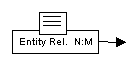
Relationships among entities can be of three
different types:
- 1 to1:
a row of a table (an object of an entity) is related to one row at most of
another table
e.g.,
the relationship capital of a country is 1 to 1
- 1 to N:
a row of a table can be related to more than one row of another table.
e.g., the relationship nationality of a student: each student has a nationality (we suppose that h/she can have only one), but there can be several students of the same nationality.
- N to M:
a row of an entity can be related to several rows of another one, and
reciprocally.
e.g., The relationship of a student being enrolled in a subject of a course is an example of this type. A student is usually enrolled in more than one subject (relation 1:N), and a subject has got several students (relation 1:M).
·
The model can be
represented graphically in the following way:
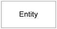
- entities as boxes with the name inside
![]()
- relationships are represented as
![]() Relationship 1:1
Relationship 1:1
![]() Relationship
1:N
Relationship
1:N
![]() Relationship
M:N
Relationship
M:N
RMDM
·
The data model
RMDM (Relationship Management Data Model)extends the E-R model for hypermedia
information systems design.
·
RMDM
distinguishes two types of primitives:
o domain primitives - model domains or classes of objects
o access primitives - support modeling for the navigation
·
Domain
primitives - RMDM includes:
o Entities
o Attributes
o one-one associative relationship
o one-many associative relationship
·
New primitive
called slice:
o denotes attributes that are grouped together (mainly
for presentation purposes).
o The graphical representation of an entity and a
specific slice is:
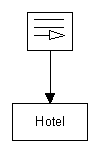
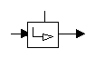
Access primitives support
navigation:
- unidirectional and bi-directional links for access
between slices of an entity
- grouping which is a construct supporting menu-like access or index,
which is a table of contents to a list of entities;
- conditional index, an index which can be qualified by a
predicate, guided tour, defined as a linear path through a
collection of items;
- conditional indexed guided tour, which represents a guided tour qualified by a
predicate.
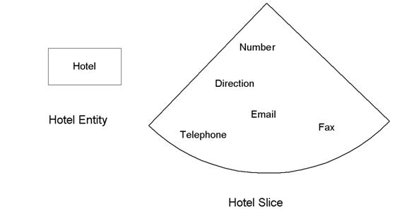
Examples:
- The hotel entity could be visited through a Conditional
Index :
- The list of the hotels (of a certain category -
which is the condition -) appears on the screen and we can choose the one
we want to see.
- The following diagram is used to represent this
type of access.
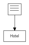
·
Conditional
Guided Tour - indicating that we go
from the first hotel to the following one and so on; we can go forwards and
backwards.
·
The graphical
representation is:
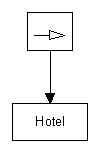
·
Conditional
Indexed Guided Tour as a hybrid
solution of an index which leads to a (partial) guided tour.
·
The
representation is:
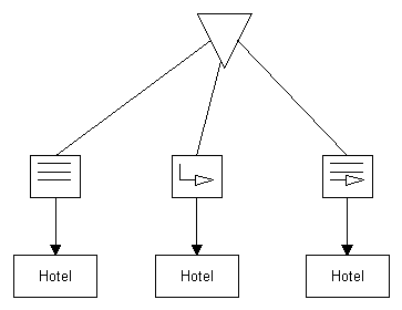
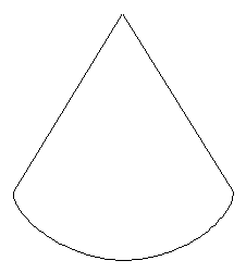
The grouping primitive is used to
model a menu: as many options as wished hang from this primitive, which is
represented as an inverted triangle.

A menu allowing the three types of access
would be represented as:
The following table is a summary of the
concepts and representations just seen:
|
Domain primitives |
Entity |
|
|
|
Attribute |
Attribute |
|
|
Slice |
|
|
Access primitives |
Index |
|
|
|
Guided tour |
|
|
|
Indexed guided tour |
|
|
|
Grouping |
|
|
|
Link |
|


·
The links,
which represent connections between slices, are also called structural
links.
·
The associative relationships
interconnect different entity instances or different entities.
·
When a user
traverses an associative link, the information context changes.
·
However, when a
structural link is traversed, the information context remains within the same
entity.
RMM
·
RMM (Relationship
Management Methodology) is a methodology for hypermedia application design
based on RMDM.
·
The different
steps of the methodology
Step 0: Feasibility and requirements analysis
Step 1: E-R design
·
An E-R diagram
is created, separating N:M relationships into two 1:N relationships.
·
Hypermedia goal
of this phase is to uncover the relationships of the objects, which potentially
will indicate navigation paths later.
·
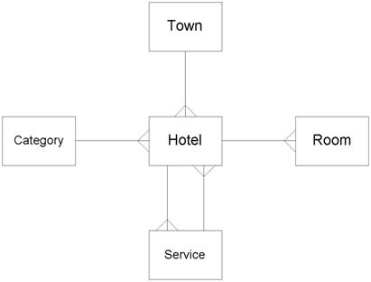
Consider an
information system of hotels in a region
·
There are five
entities: Hotel, Town, Service, Room and Category;
·
the town-hotel,
category-hotel, hotel-room are 1:N relationships
·
service-hotel is
a N:M relationship
Step 2: Slice design
·
The attributes
of an entity are divided into slices.
·
Structural links
for navigation between slices are defined
·
Hypermedia point
of view is that of the navigation.
·
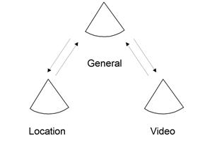
e.g.,
o all hotel information could be in the same slice (we
would need a window with scrolling to be able to show that)
o alternative - general information in a slice, with
another slice containing the name and multimedia material (e.g., video).
o alternative - general information is too complex -
choose a summary slice, and two other slices containing detailed textual
information and multimedia information.
·
RMDM introduces
the concept of slice head - default access to an entity
·
an example of
hotel slices:
|
General * (head) |
Name |
|
|
Address |
|
|
Telephone |
|
|
Fax |
|
|
E-mail |
|
|
URL |
|
|
Number of floors |
|
|
Date of construction |
|
|
Number of rooms |
|
Situation |
How to get there |
|
|
Distance to the beach |
|
|
Distance to the airport |
|
|
Distance to the main city |
|
|
Distance to the bus stop |
|
Multimedia |
Video |
·
The structural
links in this case could be as:
Step 3: Navigational design
·
Relationships
obtained in step 1 are replaced by RMDM access primitives.
·
Slice heads are
defined in this step.
·
Suggestions
about structure:
o A guided tour is not advisable when there is a large
number of instances, but it might be convenient for a small number.
o An index should help when there is a large number;
and a conditional guided tour could be a compromise.
o Group primitives are used for menus.
o Although a hierarchy can be created, extensive depth
is counterintuitive for most users.
·
Final result is
in the RMDM diagram below.
o The following diagram corresponds to an index for
hotel-service and category-hotel, a guided tour for hotel-room and an indexed
guided tour for town-hotel.
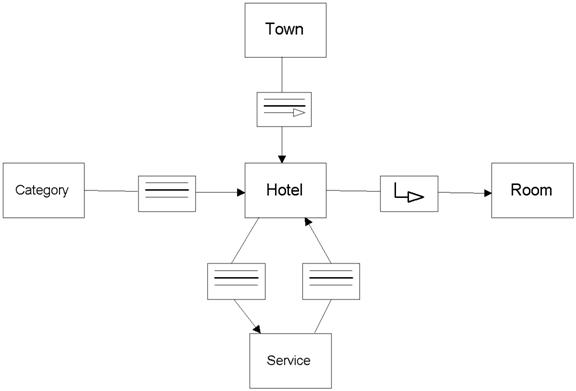
o Most "backwards" links are not explicit in
this diagram, because they would be too redundant
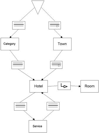
o Grouping for menus example - enable access either
through towns (via conditional index) or hotel category (via index).
o This would be represented as:
Step 4: Conversion protocols design
o Steps 4 to 6 can be performed simultaneously from the
RMDM diagram.
o Step 4 defines how to transform each RMDM element
into the hardware-software platform chosen.
Step 5: User interface design
o Graphical designs of screens that represent the RMDM
elements are obtained.
o Important issues: slices, access structures, general
navigation tools, anchor appearance, ...
o Prototyping in low-fidelity (paper) or high-fidelity
(photoshop) should be of help.
Step 6: Run-time behaviour design
o Defining the mechanisms (algorithms) to be
implemented for traversing links, for keeping history, to allow backtracking,
...
Step 7: Construction and testing
o This phase is the effective construction of
databases, algorithm implementation, ...
o Testing.
RMM and RMDM
modifications and improvements
Modifications proposed by the authors of
RMM and RMDM
o Several modifications and improvements to the data
model RMDM and methodology RMM.
o Hybrid slices - combine attributes from different entities and access structures
o minimal slices - the minimal meaningful way of referring to a slice.
o Limitations of RMM (from Russian Dolls and
Hypertext):
o Inability to specify what information is to be shown
as the content of an anchor
o Inability to allow aggregation of attributes outside
a single entity
o No element can contain both attributes and access
structures
o Solution - introduce m-slices - used to group
information into meaningful units, replacing slices and group constructs.
o M-slices are owned (each by one specific entity)
although they might contain attributes of other entities and access structures.
o They define what information is to be part of a
construct and where to obtain it.
o M-slices do not say how this information is to be
presented.
o They can be nested up to arbitrary levels.
o Also anchoring is supported.
Modifications introduced in the CD-ROM Atles de les Illes Balears
o Toni Navarrete introduced some modifications both to
RMM and RMDM in his work for the Atles de les Illes Balears.
|
|
Hyperlink inferred in hierarchical
relationships 1:N |
|
|
Random access |
|
|
Simultaneous access |
|
|
Multiple index |
|
|
Multiple guided tour |
|
|
Multiple indexed guided
tour |
|
|
Access in relationships
N:M |
HDM
·
The authors of
HDM (Hypertext Design Model) were Garzotto, Paolini and Schwabe.
·
The model should
be useful to design a hypertext or hypermedia application.
·
Use the
following terminology:
o authoring-in-the-large - denotes the specifications and design of the
global or structural aspects of the application
o authoring-in-the-small - denotes the aspects of development of the content
of the nodes.
HDM primitives
Entities and entity types
- An entity is a hierarchically structured
collection of components, in a tree structure
·
Entities are information chunks of reasonable although
minimal size, which are meaningful autonomously.
·
Entities are
grouped into entity types.
e.g. Painter, Artists' Live, Picture type, Subject.
·
Each entity is
made of a hierarchy of components
·
Entities cannot be
components of other entities.
- Components can be made of units.
- Units are the smallest pieces of information
and can be visualized from a specific perspective.
- The notion of perspective allows for different
presentations of the same content.
- e.g, in a multi-lingual presentation, the
different languages give different perspectives.
The
logical structure of the presentation is not altered.
- Most common relationship is part-all.
- Units are information containers and components
are abstractions of sets of components.
- A unit corresponds to a component associated to
a specific perspective.
- A unit is characterised by its name (an identifier)
and a body.
- The bodies are the locations where the
information is stored; a unit usually combines atomic parts of information
which are shown together.
Links and types of links
- Links
are primitives in HDM
- Three types of links:
- Structural links are those connecting together components of
the same entity
- Perspective or component links are those connecting different units of the
same component.
- Applicative links denote domain
dependent relationships
- Two broad categories:
- schema links, which have pre-defined syntactic and
semantic features
- generic links, which are more specific.
- e.g.,
- if there is an entity type Historical Period,
and another one Painter, an applicative link might go from Goya to
XVIII and XIX Century
- this link would be a schema link, as each
painter will be linked to his/her historical period.
- A generic link maygo from Goya to Duquesa de
Alba
- Perspective, Structural and Schema links are
automatically derived from the structure
- Perspective, structural and applicative links
will have names, and will be specifically typed.
- The schema link could be called Historical period
of the painter
Collections
- Collections are ordered sets of objects (entities, components, other
collections).
- Used mainly for navigation.
- In HDM there is a special one, dynamically
generated, which is the ordered set of units visited.
Schemas
- HDM specification of a hypertext application
consists of a schema definition
- A schema definition specifies a set of
entity types and link types; and a set of instance definitions
- An instance definition is is only allowed to be
inserted if the instance matches the constraints of the schema.
Outlines
- An application in HDM can be divided into: a hyperbase
of the structured nodes, links, and a set of access structures
- Access structures give entry points for navigation.
- The only access structure defined in HDM is the outline, which is a tree for the main access of the hyperbase.
HDM structure and
browsing semantics
- Entity types, structural and schema links, and
collections belong to structure-in-the-large
- Units and perspective links belong
structure-in-the-small.
- Links maybe automatically generated.
- Structural link operators are up, down, upN,
downN, ... would create automatic patterns.
- Operators such as inversion, composition, ...
would enable the computation of derived links and even of derived link
types.
- Default browsing semantics: units are
identified as nodes (loci of navigation control) and perspective links
enable navigation from the nodes.
- There is a default representative of each unit,
... and a default perspective; links become thus concrete.
- Structural links become links between
corresponding perspectives of linked components.
- The structure-in-the-large is made of the
general organization (a set of collections) and structural and schema
links.
- The dynamics-in-the-large is the definition of:
the navigation of the collection, which can be through visiting one member
after the other - guided tour - or by index; and the structural and schema
link navigation.
OOHDM - Object-Oriented Hypermedia
Design Method
Evolution of HDM
·
Model-based
approach for building hypermedia applications
- Comprises five different activities: requirements
gathering, conceptual design, navigational design, abstract
interface design and implementation.
- See paper Systematic Hypermedia Application
Design with OOHDM (http://www-di.inf.puc-rio.br/schwabe/HT96WWW/section1.html)
, where the authors (Schwabe, Rossi, Barbosa) describe it using an
example, the Portinari Project about a famous Brazilian painter, as
illustration.
·
Each step
focuses on a particular design concern, and an object-oriented model is built.
Classification, aggregation and generalization/specialization are used
throughout the process to enhance abstraction power and reuse opportunities.
·
The table below
summarizes the steps, products, mechanisms and design concerns in OOHDM.
|
Activities |
Products |
Formalisms |
Mechanisms |
Design
Concerns |
|
Requirements Gathering |
Use Cases, Annotations |
Scenarios; User Interaction Diagrams; Design Patterns |
Scenario and Use Case Analysis, Interviews, UID mapping to
Conceptual Model |
Capture the stakeholder requirements for the application. |
|
Conceptual Design |
Classes, sub-systems, relationships, attribute
perspectives |
Object-Oriented Modeling constructs; Design Patterns |
Classification, aggregation, generalization and
specialization |
Model the semantics of the application domain |
|
Navigational Design |
Nodes, links, access structures, navigational contexts,
navigational transformations |
Object-Oriented Views; Object-Oriented State charts;
Context Classes; Design Patterns; User Centered Scenarios |
Classification, Aggregation, generalization and specialization. |
Takes into account user profile and task. Emphasis on
cognitive aspects. Build the navigational structure of the application |
|
Abstract Interface Design |
Abstract interface objects, responses to external events,
interface transformations |
Abstract Data Views; Configuration Diagrams; ADV-Charts;
Design Patterns |
Mapping between navigation and perceptible objects |
Model perceptible objects, implementing chosen metaphors.
Describe interface for navigational objects. Define lay-out of interface
objects |
|
Implementation |
Running application |
Those supported by the target environment |
Those provided by the target environment |
Performance, completeness |
1
Requirements Gathering
·
The first step
is to gather the stakeholder requirements.
·
Necessary to
first identify the actors (stakeholders) and the tasks they must perform.
·
Scenarios are
collected (or drafted), for each task and type of actor.
·
Scenarios are
then collected to form a Use Case, which is represented using User Interaction
Diagrams.
o These diagrams provide a concise graphical
representation of the interaction between the user and the system during the
execution of a task.
·
The UIDs are
validated with the actors, and redesigned if necessary.
·
In sequence, a
set of guidelines are applied to the UIDs to extract a conceptual model.
2 Conceptual Design
- A model of the application domain is built using
object-oriented modeling principles (OMT), augmented with some primitives
such as attribute perspectives and sub-systems.
- Must capture the domain semantics as
"neutrally" as possible, with very little concern for the types
of users and tasks.
- Product of this step - a class and instance
schema built out of Sub-Systems, Classes and Relationships.
- Portinari Project example - classes are
Artwork, Interview, ...
- An attribute of Artwork is Description, which
has two perspectives - Text and Picture.
- There is a parallel with the concepts of HDM
(entity types, components, perspectives, ...)
- The figure shows (a simplified version of) the
conceptual schema for the Portinari Project, where, for the sake of
conciseness, all attributes of all classes are not shown.

The conceptual
schema for the "Portinari Project"
3 Navigational Design
- Navigation design is expressed in two schemas -
the navigational class schema, and the navigation context schema.
- For the navigational class schema, there is a
set of pre-defined types of navigational classes: nodes, links,
and access structures (indexes and guided tours, ...).
- In OOHDM, nodes are defined as object-oriented
views of the conceptual classes defined previously.
- The node can be defined by combining attributes
of different related classes in the conceptual schema.
- They contain single typed attributes and link anchors,
and may be atomic or composites.
- Links are also defined as views on relationships
in the conceptual schema.
- The relationships which are interesting for the
users are transformed into access structures.
- The second part of the navigational design proceeds
after introducing the notion of navigational context, which is a set of nodes,
links, context classes and other (nested) navigational
contexts.
- Navigational contexts play a similar role as
collections in HDM. Somehow, they allow to introduce the contexts (to
encapsulate the way the user navigates the application).
- The figure shows three navigational class
definitions for the example.
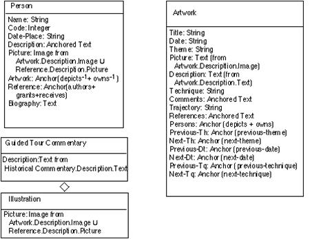
Figure: Navigational Class Schema for the Portinari Project
application
4 Abstract Interface Design
- Define the objects the user will perceive (e.g.
a picture, a city map, etc.) in terms of interface classes
- Interface classes are defined as aggregations of
primitives classes (such as text fields and buttons) and recursively of
interface classes.
- Interface objects map to navigational objects,
providing a perceptible appearance.
- Interface behavior is declared by specifying how
to handle external and user-generated events and how communication takes
place between interface and navigational objects.
·
Must design the
way in which navigational objects will appear, which objects will activate
navigation, the way in which multimedia objects will be synchronized and which
transformations will take place, all at the visualization level, and thus we
call those objects interface objects to differentiate them from the conceptual
or navigational objects.
·
OOHDM uses
Abstract Data Views - formal, object-oriented models of interface objects and
they are specified by showing:
-
the static
lay-out structure that implements the interface (with all the elements,
including menus, ...), with perception properties as attributes or parts of an
ADV
-
- how interface
objects are related to navigation objects: Configuration Diagrams are used for
that
-
how interface
objects behave when reacting to external events; ADV-Charts that add both
structural and behavioral nesting are used;
-
Petri-Net like
notation is used for expressing synchronization issues.
5 Implementation
Map the navigational and abstract interface
models into concrete objects available in the chosen implementation environment
(or possible to build).