CS865 – Distributed Software
Development
|
|
Lecture 2 |
Tannenbaum and Van
Steen – Chapter 2
Architectures
Architectural Styles
Software architecture - logical organization of distributed
systems into software components
Architectural style:
·
Types of components
·
The way that components are connected
·
The data exchanged between components
·
How these elements are jointly configured into a system.
Software component - a modular unit with
well-defined, required and provided interfaces that is replaceable within its environment (OMG, spec).
Connector - a mechanism that mediates communication, coordination, or cooperation among components (Mehta et al., 2000; and Shaw and Clements, 1997 table).
e.g. a connector can be formed by the facilities for (remote) procedure calls, message passing, or streaming data.
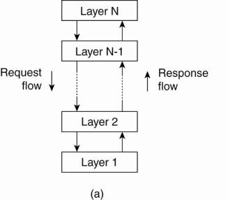
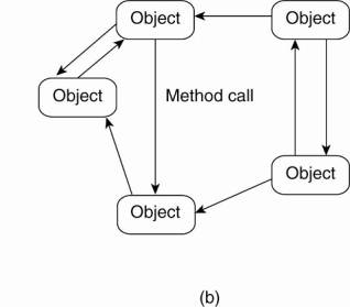
Architectural styles for distributed systems are:
1. Layered
architectures
The (a) layered and (b)
object-based architectural style.
2. Object-based
architectures
·
each object corresponds a component
·
components are connected through a (remote) procedure call
mechanism.
(The layered and object-based architectures still form the most important styles for large software systems)
3. Data-centered
architectures
·
processes communicate through a common (passive or active)
repository
·
e.g.
§
wealth of networked applications have been developed that
rely on a shared distributed file system in which virtually all communication
takes place through files.
§
Web-based distributed systems are largely data-centric:
processes communicate through the use of shared Web-based data services.
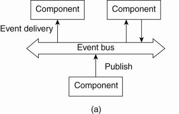
4. Event-based
architectures
o processes
communicate through the propagation of events
o e.g.
publish/subscribe systems (Eugster
et al., 2003).
§
processes publish events after which the middleware ensures
that only those processes that subscribed to those events will receive them.
o advantage
- processes are loosely coupled. In principle, they need not explicitly refer
to each other. This is also referred to as being decoupled in space, or
referentially decoupled.
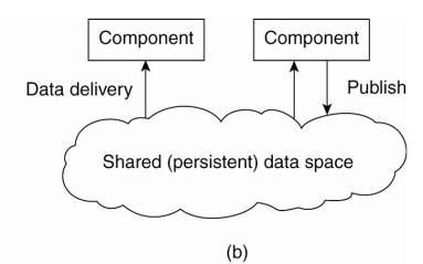
Shared data spaces – combination of event-based
architectures with data-centered architectures.
o processes
are decoupled in time: they need not both be active when communication takes
place.
o many
shared data spaces use a SQL-like interface to the shared repository - data can
be accessed using a description rather than an explicit reference,
as is the case with files.
The (a) event-based and (b) shared data-space architectural
style.
Aim of Architectures:
achieving distribution transparency.
System
Architectures
Centralized
Architectures
Manage distributed system complexity - think
in terms of clients that request services from servers.
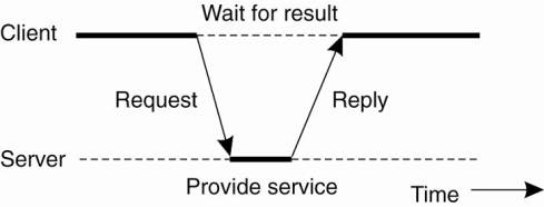
Basic client-server model:
o Processes are divided into two groups:
1.
A server is a process implementing a specific service, for
example, a file system service or a database service.
2.
A client is a process that requests a service from a server
by sending it a request and subsequently waiting for the server's reply.
o General
interaction between a client and a server.
Communication - implemented using a connectionless
protocol when the network is reliable -> e.g. local-area networks.
1.
Client requests a service – packages and sends a message for
the server, identifying the service it wants, along with the necessary input
data.
2.
The Server will always wait for an incoming request, process
it, and package the results in a reply message that is then sent to the client.
Connectionless protocol
o Describes
communication between two network end points in which a message can be sent
from one end point to another without prior arrangement.
o Device at
one end of the communication transmits data to the other, without first
ensuring that the recipient is available and ready to receive the data.
o The device
sending a message sends it addressed to the intended recipient.
o More frequent
problems with transmission than with connection-orientated protocols and it may
be necessary to resend the data several times.
o making the
protocol resistant to occasional transmission failures is not trivial.
o the client
cannot detect whether the original request message was lost, or that
transmission of the reply failed.
§
If the reply was lost, then resending a request may result
in performing the operation twice
·
e.g. If operation was "transfer $10,000 from my bank
account," then clearly, it would have been better that we simply reported
an error instead.
§
When an operation can be repeated multiple times without
harm, it is said to be idempotent
o Often
disfavored by network administrators because it is much harder to filter
malicious packets from a connectionless protocol using a firewall.
o e.g.
connectionless protocols -The Internet Protocol (IP) and User Datagram Protocol
(UDP) are connectionless protocols,
o Alternative
- connection-oriented protocol ( TCP/IP -the most common use of IP)
o not
appropriate in a local-area network due to relatively low performance
o works fine
in wide-area systems in which communication is inherently unreliable.
o e.g.
virtually all Internet application protocols are based on reliable TCP/IP
connections.
§
whenever a client requests a service, it first sets up a
connection to the server before sending the request.
§
The server uses that same connection to send the reply
message, after which the connection is torn down.
§
Problem: setting up and tearing down a connection is
relatively costly, especially when the request and reply messages are small.
Application
Layering
Issues with Client / Server:
o How to
draw a clear distinction between a client and a server.
o Often no
clear distinction.
o e.g. a
server for a distributed database may continuously act as a client because it
is forwarding requests to different file servers responsible for implementing
the database tables.
Since many client-server applications are targeted toward
supporting user access to databases, distinctions may be analyzed in a layered
architectural style:
1.
The user-interface level -
contains all that is necessary to directly interface with the user, such as
display management
o Clients
typically implement the user-interface level
o simplest
user-interface program - character-based screen
§
the user's terminal does some local processing such as
echoing typed keystrokes, or supporting form-like interfaces in which a complete
entry is to be edited before sending it to the main computer
o Simple GUI
§
pop-up or pull-down menus are used with many screen controls
handled through a mouse instead of the keyboard.
o Modern
user interfaces offer considerably more functionality by allowing applications
to share a single graphical window, and to use that window to exchange data
through user actions.
2.
The processing level -
contains the applications
o middle
part of hierarchy -> logically placed at the processing level
3.
The data level - manages the actual data that is
being acted on
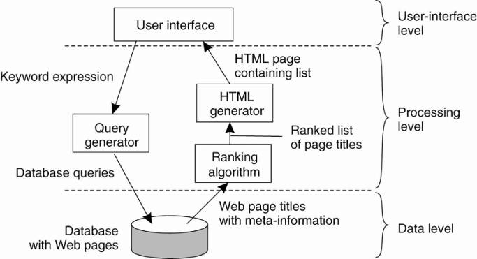
Example: Internet search engine
·
User-interface level: a user
types in a string of keywords and is subsequently presented with a list of
titles of Web pages.
·
Data Level: huge database of Web pages that
have been prefetched and indexed.
·
Processing level: - search engine that
transforms the user's string of keywords into one or more database queries.
o ranks the
results into a list
o transforms that list into a series of HTML
pages
Simplified organization of an Internet search engine into
three different layers.
Client-Server Model – Data Level
·
Contains the programs that maintain the actual data on which
the applications operate.
·
Data are often persistent - even if no application is
running, data will be stored somewhere for next use.
·
Data level consists of a file system, but it is more common
to use a full-fledged database.
·
Data level is typically implemented at the server side.
·
Responsible for keeping data consistent across different
applications.
o With
databases - metadata such as table descriptions, entry constraints and
application-specific metadata are also stored at this level.
·
Relational database organize most business-oriented data.
o Data
independence is crucial
·
data are organized independent of the applications in such a
way that changes in that organization do not affect applications, and neither
do the applications affect the data organization.
o Using
relational databases in the client-server model helps separate the processing
level from the data level, as processing and data are considered independent.
·
Other Data base choices –
o many
applications operate on complex data types that are more easily modeled in
terms of objects than in terms of relations.
o implement the data level by means of an object-oriented
or object-relational database.
§
built upon the widely dispersed relational data model, while
offering the advantages ofobject-orientation.
Multitiered
Architectures
Possibilities for physically distributing a client-server
application across several machines.
·
Simplest organization - two types of machines:
1.
A client machine containing only the programs implementing
(part of) the user-interface level
2.
A server machine containing the rest, that is the programs
implementing the processing and data level
o Everything
is handled by the server while the client is essentially no more than a dumb
terminal, possibly with a pretty graphical interface.
·
Distribute the programs in the application layers
across different machines [Jing et
al. (1999) ].
o Two-tiered
architecture: client machines and server machines.
o Alternative
client-server organizations (a)–(e).
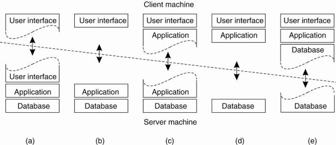
Cases:
A: only the terminal-dependent part of the user interface
on the client machine
B: place the entire user-interface software on the
client side
o Divide the
application into a graphical front end, which communicates with the rest of the
application (residing at the server) through an application-specific protocol.
o the front
end (the client software) does no processing other than necessary for
presenting the application's interface
C: move part of the application to the front end
o e.g. the
application makes use of a form that needs to be filled in entirely before it
can be processed
o front end
can then check the correctness and consistency of the form, and where necessary
interact with the user
D: used where the client machine is a PC or
workstation, connected through a network to a distributed file system or database
o most of
the application is running on the client machine, but all operations on files
or database entries go to the server
o e.g. many
banking applications run on an end-user's machine where the user prepares
transactions and such
Once finished, the application contacts the database on the bank's server and uploads the transactions for further processing
E: used where the client machine is a PC or
workstation, connected through a network to a distributed file system or
database
o the
situation where the client's local disk contains part of the data
Issues:
Trend to move away from the configurations D and E.
o Although
client machines do a lot, they are also more problematic to manage
o Having
more functionality on the client machine makes client-side software more prone
to errors and more dependent on the client's underlying platform (i.e.,
operating system and resources).
o From a system's management perspective, having fat clients is not optimal.
o Thin
clients in A – C are much easier
Trend: server-side solutions are becoming increasingly more
distributed as a single server is being replaced by multiple servers running on
different machines.
o a server
may sometimes need to act as a client leading to a (physically) three-tiered
architecture.
o Example of
a server acting as client.
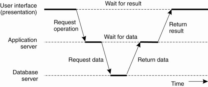
o Programs
that form part of the processing level reside on a separate server, but may
additionally be partly distributed across the client and server machines.
o e.g. three-tiered architecture - organization of
Web sites.
§
Web server acts as an entry point to a site, passing
requests to an application server where the actual processing takes place.
§
Application server interacts with a database server.
·
e.g., an application server may be responsible for running
the code to inspect the available inventory of some goods as offered by an
electronic bookstore. To do so, it may need to interact with a database
containing the raw inventory data.
Decentralized
Architectures
Vertical Distribution Architecture
o Achieved
by placing logically different components on different machines
o term is
related to the concept of vertical fragmentation
as used in distributed relational databases, where it means that tables are
split column-wise, and subsequently distributed across multiple machines
o Multitiered
client-server architectures are a direct consequence of dividing applications
into a user-interface, processing components, and a data level. The different
tiers correspond directly with the logical organization of applications.
o Vertical
Distribution - organizing a client-server application as a multitiered
architecture.
o Can help
manage distributed systems by logically and physically splitting functions
across multiple machines, where each machine is tailored to a specific group of
functions.
Horizontal Distribution Architecture
o Client or
server may be physically split up into logically equivalent parts, but each
part is operating on its own share of the complete data set, thus balancing the
load.
o e.g peer-to-peer systems.
o Processes
that constitute a peer-to-peer system are all equal.
o Functions
that need to be carried out are represented by every process that constitutes
the distributed system.
o Much of
the interaction between processes is symmetric:
o each
process will act as a client and a server at the same time (which is also
referred to as acting as a servent).
o Peer-to-peer
architectures - how to organize the processes in an overlay network in which
the nodes are formed by the processes and the links represent the possible
communication channels (which are usually realized as TCP connections).
o A Process
cannot communicate directly with an arbitrary other process, but is required to
send messages through the available communication channels.
o Two types
of overlay networks exist: those that are structured and those that are not. (Castro
et al. 2005).
o Survey
paper (Lua
et al. 2005).
o A
reference architecture that allows for a more formal comparison of the
different types of peer-to-peer systems (Aberer
et al. 2005) provide a reference architecture that allows for a more formal
comparison of the different types of peer-to-peer systems.
o A survey
taken from the perspective of content distribution is provided by (Androutsellis-Theotokis
and Spinellis 2004).
Structured
Peer-to-Peer Architectures
o The P2P overlay
network consists of all the participating peers as network nodes.
o There are
links between any two nodes that know each other: i.e. if a participating peer
knows the location of another peer in the P2P network, then there is a directed
edge from the former node to the latter in the overlay network.
o Based on
how the nodes in the overlay network are linked to each other, we can classify
the P2P networks as unstructured or structured.
o Some well
known structured P2P networks are Chord,
Pastry, Tapestry, CAN, and Tulip.
o A
structured Peer-to-Peer overlay network is constructed using a deterministic
procedure.
o Most-used
procedure - organize the processes through a distributed hash
table (DHT). (Hash Table description)
o DHT-based system –
o data
items are assigned a random key from a large identifier space, such as a
128-bit or 160-bit identifier.
o nodes are assigned a random number from the same identifier space.
o DHT-based system implements an efficient and deterministic scheme that uniquely maps the key of a data item to the identifier of a node based on some distance metric (Balakrishnan, 2003).
o When
looking up a data item, the network address of the node responsible for that
data item is returned.
o This is
accomplished by routing a request for a data item to the responsible node.
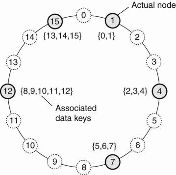
Example: Chord system (Stoica
et al., 2003) the nodes are logically organized in a ring such that a data
item with key k is mapped to the node with the smallest identifier idk.
o This node
is referred to as the successor of key k and denoted as succ(k)
o To look up
the data item an application running on an arbitrary node would then call the
function LOOKUP(k) which would subsequently return the network address of
succ(k). At that point, the application can contact the node to obtain a copy
of the data item.
The mapping of data items onto nodes in Chord.
How do nodes organize themselves into an overlay
network?
o Looking up
a key does not follow the logical organization of nodes in the ring.
o Each node
will maintain shortcuts to other nodes in such a way that lookups can generally
be done in Ο(log (N)) number of steps, where N is the number of nodes
participating in the overlay.
Joining the P2P Network
1.
When a node wants to join the system, it starts with
generating a random identifier id.
2.
Then, the node can simply do a lookup on id, which will
return the network address of succ(id).
3.
The joining node then contacts succ(id) and its predecessor
and insert itself in the ring.
a.
This scheme requires that each node also stores information
on its predecessor.
b.
Insertion also yields that each data item whose key is now
associated with node id, is transferred from succ(id).
Leaving the P2P Network
1.
node id informs its departure to its predecessor and
successor
2.
transfers its data items to succ(id).
Content Addressable Network (CAN)
– (Ratnasamy
et al. 2001).
·
CAN deploys a d-dimensional Cartesian coordinate space,
which is completely partitioned among all all the nodes that participate in the
system.
·
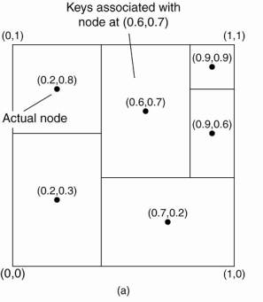
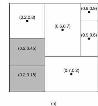
Example: 2-dimensional case
(a) The mapping of data items onto nodes in CAN. (b) Splitting a region when a node joins.
·
Two-dimensional space [0,1]x[0,1] is divided among six
nodes.
·
Each node has an associated region.
·
Every data item in CAN will be assigned a unique point in
this space, after which it is also clear which node is responsible for that
data (ignoring data items that fall on the border of multiple regions, for
which a deterministic assignment rule is used).
Joining CAN
·
When a node P wants to join a CAN system, it picks an
arbitrary point from the coordinate space and subsequently looks up the node Q
in whose region that point falls.
·
Node Q then splits its region into two halves and one half
is assigned to the node P.
·
Nodes keep track of their neighbors, that is, nodes
responsible for adjacent region.
·
When splitting a region, the joining node P can easily come
to know who its new neighbors are by asking node P.
·
As in Chord, the data items for which node P is now
responsible are transferred from node Q.
Leaving CAN
·
Assume that the node with coordinate (0.6,0.7) leaves.
·
Its region will be assigned to one of its neighbors, say the
node at (0.9,0.9), but it is clear that simply merging it and obtaining a
rectangle cannot be done.
·
In this case, the node at (0.9,0.9) will simply take care of
that region and inform the old neighbors of this fact.
·
This may lead to less symmetric partitioning of the
coordinate space, for which reason a background process is periodically started
to repartition the entire space.
Unstructured
Peer-to-Peer Architectures (Risson
and Moors, 2006).
·
An unstructured P2P network is formed when the overlay links
are established arbitrarily.
·
Such networks can be easily constructed as a new peer that
wants to join the network can copy existing links of another node and then form
its own links over time.
·
In an unstructured P2P network, if a peer wants to find a
desired piece of data in the network, the query has to be flooded through the
network in order to find as many peers as possible that share the data.
·
Main disadvantage - queries may not always be resolved.
·
Popular content is likely to be available at several peers
and any peer searching for it is likely to find the same thing, but, if a peer
is looking for a rare or not-so-popular data shared by only a few other peers,
then it is highly unlikely that search will be successful.
·
Since there is no correlation between a peer and the content
managed by it, there is no guarantee that flooding will find a peer that has
the desired data.
·
Flooding also causes a high amount of signaling traffic in
the network and hence such networks typically have very poor search efficiency.
·
Most of the popular P2P networks such as Napster, Gnutella
and KaZaA are unstructured.
·
Rely on randomized algorithms for constructing an overlay
network.
·
Each node maintains a list of neighbors constructed in a
more or less random way.
·
Data items are assumed to be randomly placed on nodes.
Goal - construct an overlay network
that resembles a random
graph. (survey)
·
Each node maintains a list of c
neighbors, where each of these neighbors represents a randomly chosen live node
from the current set of nodes.
·
The list of neighbors is referred to as a partial view.
·
Many ways to construct a partial view. (Jelasity et al. 2004).
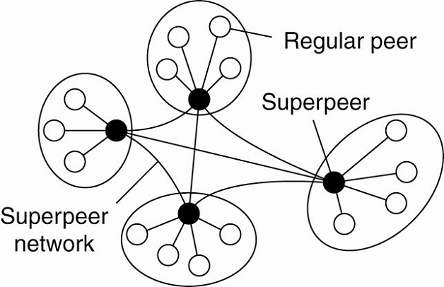
Superpeers (overview)
Network nodes that maintaining an index of node or acting as
a broker for nodes are generally referred to as superpeers.
Unstructured peer-to-peer systems - locating relevant data
items can become problematic as the network grows.
· no deterministic way of routing a lookup request to a specific data item -> only technique a node can resort to is flooding the request.
·
flooding can be dammed-> alternative -> use special
nodes that maintain an index of data items.
Other situations in which abandoning the symmetric nature of
peer-to-peer systems is sensible.
·
Example: collaboration of nodes that offer resources to each
other.
§
in a collaborative content delivery network (CDN), nodes may
offer storage for hosting copies of Web pages allowing Web clients to access
pages nearby, and thus to access them quickly.
§
A node P may need to seek for resources in a specific part
of the network.
§
Making use of a broker that collects resource usage for a
number of nodes that are in each other's proximity will allow to quickly select
a node with sufficient resources.
A hierarchical organization of nodes into a superpeer
network.
·
The client-superpeer relation is fixed n many cases:
whenever a regular peer joins the network, it attaches to one of the superpeers
and remains attached until it leaves the network.
·
Expected that superpeers are long-lived processes with a
high availability.
·
To compensate for potential unstable behavior of a superpeer,
backup schemes can be deployed, such as pairing every superpeer with another
one and requiring clients to attach to both.
Hybrid
Architectures
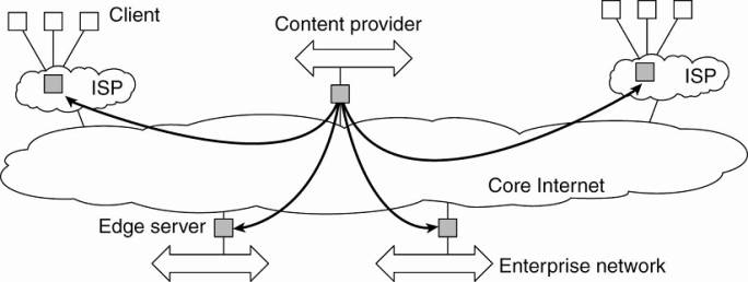
Edge-Server Systems
·
Deployed on the Internet where servers are placed "at
the edge" of the network.
§
purpose is to serve content, possibly after applying
filtering and transcoding functions
§
a collection of edge servers can be used to optimize content
and application distribution
·
This edge is formed by the boundary between enterprise
networks and the actual Internet
§
e.g, an Internet Service Provider (ISP).
§
e.g. end users at home connect to the Internet through their
ISP, the ISP can be considered as residing at the edge of the Internet.
o Viewing
the Internet as consisting of a collection of edge servers.
Basic model - one edge server acts as an
origin server from which all content originates.
That server can use other edge
servers for replicating Web pages and such (Leff et
al., 2004; Nayate et al., 2004).
Collaborative
Distributed Systems
o Hybrid
architectures are deployed in collaborative distributed systems.
o Two step
process:
1.
Join system using a traditional client-server scheme.
2.
Once a node has joined the system - use a fully
decentralized scheme for collaboration.
Example: the BitTorrent file-sharing
system (Cohen,
2003).
o BitTorrent
is a peer-to-peer file downloading system.
o An end
user downloads chunks of a file from other users until the downloaded chunks
can be assembled together yielding the complete file.
o BitTorrent
combines centralized with decentralized solutions.
o The
principal working of BitTorrent
o Design
goal - ensure collaboration.
1.
Most file-sharing systems - participants download files only
(Adar
and Huberman, 2000; Saroiu
et al., 2003; and Yang et
al., 2005).
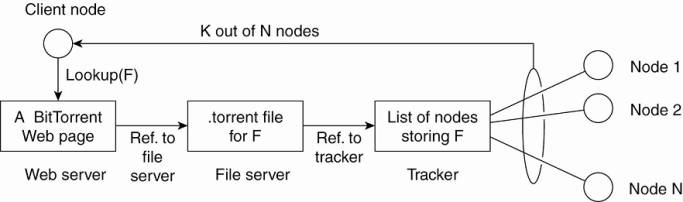
File download process:
1.
Access a global directory of one of a few well-known Web
sites.
o Directory
contains references to what are called .torrent files.
o A .torrent
file contains the information that is needed to download a specific file.
o It refers
to a tracker - a server that keeps an accurate
account of active nodes that have (chunks) of the requested file.
o An active
node is one that is currently downloading another file.
o Many
different trackers - but only a single tracker per file (or collection of
files).
2.
Once the nodes have been identified from where chunks can be
downloaded - the downloading node becomes active.
o This node
will be forced to help others by providing chunks of the file it is downloading
that others do not yet have.
o Enforcement
comes from a very simple rule: if node P notices that node Q is downloading
more than it is uploading, P can decide to decrease the rate at which it sends
data to Q.
o This
scheme works well provided P has something to download from Q.
o For this
reason, nodes are often supplied with references to many other nodes putting
them in a better position to trade data.
System bottleneck is formed by the trackers.
Example:
the Globule (paper)
collaborative content distribution network.
o Globule
strongly resembles the edge-server architecture.
o Instead of
edge servers, end users (but also organizations) voluntarily provide enhanced
Web servers that are capable of collaborating in the replication of Web pages.
o Each such
server has the following components:
1.
A component that can redirect client requests to other
servers.
2.
A component for analyzing access patterns.
3.
A component for managing the replication of Web pages.
Architectures
Versus Middleware
o Middleware
forms a layer between applications and distributed platforms
o Provide a
degree of distribution transparency,hiding the distribution of data,
processing, and control from applications.
o Where
middleware fits in?
Middleware systems follow a specific architectural style
o Object-based
architectural style - CORBA
o Event-based
architectural style - TIB/Rendezvous
Problems:
o Molding
middleware molded to a specific architectural style makes designing
applications simpler BUT the middleware may no
longer be optimal for what an application developer had in mind.
o Middleware
is meant to provide distribution transparency, BUT
specific solutions should be adaptable to application requirements.
Solutions:
o Good: Make
several versions of a middleware system, where each version is tailored to a
specific class of applications.
o Better: Make
middleware systems that are easy to configure, adapt, and customize as needed
by an application.
Results:
o Systems
are now developed with a stricter separation between policies and mechanisms.
o Led to
mechanisms by which the behavior of middleware can be modified (Sadjadi
and McKinley, 2003).
o Commonly
followed approach:
Interceptors
o An interceptor is a software construct that will break
the usual flow of control and allow other (application specific) code to be
executed.
Example: consider interception as
supported in many object-based distributed systems.
o An object
A can call a method that belongs to an object B, while the latter resides on a
different machine than A.
o This
remote-object invocation is carried out in 3 steps:
o
1. Object A is offered a local interface that is exactly the same
as the interface offered by object B. A simply calls the method available in
that interface.
2. The call by A is transformed into a generic object invocation,
made possible through a general object-invocation interface offered by the
middleware at the machine where A resides.
3. Finally, the generic object invocation is transformed into a
message that is sent through the transport-level network interface as offered
by A's local operating system.
Using interceptors to handle remote-object invocations.
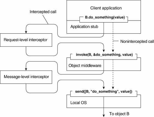
Above Figure:
1.
After the first step, the call B.do_something(value)
is transformed into a generic call such as invoke(B, &do_something, value)
with a reference to B's method and the parameters that go along with the call.
2.
Assume that object B is replicated.
·
Here, each replica should be invoked.
3.
Interception helps here the request-level interceptor will
call invoke(B, &do_something, value) for
each of the replicas.
·
Object A need not be aware of the replication of B
·
The object middleware need not have special components that
deal with this replicated call.
·
Only the request-level interceptor, which may be added to
the middleware needs to know about B's replication.
·
A call to a remote object will have to be sent over the
network.
·
The messaging interface as offered by the local operating
system will need to be invoked.
·
At that level, a message-level interceptor may assist in
transferring the invocation to the target object.
o Example:
§
imagine that the parameter value actually corresponds to a
huge array of data.
§
may be wise to fragment the data into smaller parts to have
it assembled again at the destination.
§
the middleware need not be aware of this fragmentation; the
lower-level interceptor will transparently handle the rest of the communication
with the local operating system.
General Approaches
to Adaptive Software
§
Environment in which distributed applications are executed
changes continuously
§
Changes include:
o mobility
o variance in
the quality-of-service of networks
o failing
hardware
o battery
drainage
o etc.
Adaptive software for middleware
Three basic techniques to come to software adaptation and
open research area (McKinley
et al. 2004):
1.
Separation of concerns
§
separate the parts that implement functionality from those
that take care of other things (known as extra functionalities) such as
reliability, performance, security, etc
§
cannot easily separate these extra functionalities by means
of modularization
§
aspect-oriented software development used to address
separation of concerns (Kiczales
et al. 1997)
2.
Computational reflection
§
the ability of a program to inspect itself and, if
necessary, adapt its behavior (Kon et
al., 2002).
3.
Component-based design
§
Supports adaptation through composition.
§
A system may either be configured statically at design time,
or dynamically at runtime.
o The latter
requires support for late binding, a technique that has been successfully
applied in programming language environments, but also for operating systems
where modules can be loaded and unloaded at will.
2.4. Self-Management in Distributed Systems
Must organize the components of a distributed system such
that monitoring and adjustments can be done
Organize distributed systems as high-level feedback-control
systems to allow automatic adaptations to changes:
§
Autonomic computing (Kephart,
2003)
§
Self-star systems (Babaoglu et al., 2005) - indicates the
variety by which automatic adaptations are being captured: self-managing,
self-healing, self-configuring, self-optimizing, etc.
The
Feedback Control Model
§
Adaptations take place by means of one or more feedback
control loops.
§
Systems that are organized by means of such loops are
referred to as feedback control systems.
§
Feedback control has since long been applied in various
engineering fields, and its mathematical foundations are gradually also finding
their way in computing systems (Hellerstein et al., 2004; and Diao
et al., 2005 Babaoglu).
§
For self-managing systems, the architectural issues are initially
the most interesting.
§
The basic idea behind this organization is :
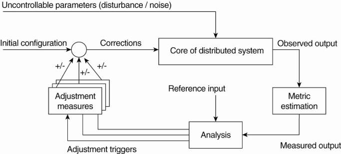
Three elements that form the feedback control loop:
1.
The system itself needs to be monitored, which requires that
various aspects of the system need to be measured.
2.
Another part of the feedback control loop analyzes the
measurements and compares these to reference values. This feedback analysis
component forms the heart of the control loop, as it will contain the
algorithms that decide on possible adaptations.
The last group of components consist of various mechanisms
to directly influence the behavior of the system. There can be many different
mechanisms: placing replicas, changing scheduling priorities, switching
services, moving data for reasons of availability, redirecting requests to
different servers, etc. The analysis component will need to be aware of these
mechanisms and their (expected) effect on system behavior. Therefore, it will
trigger one or several mechanisms, to subsequently later observe the effect.
An interesting observation is that the feedback control loop
also fits the manual management of systems. The main difference is that the
analysis component is replaced by human administrators. However, in order to
properly manage any distributed system, these administrators will need decent
monitoring equipment as well as decent mechanisms to control the behavior of
the system. It should be clear that properly analyzing measured data and
triggering the correct actions makes the development of self-managing systems so
difficult.
It should be stressed that Fig. 2-16 shows the logical
organization of a self-managing system, and as such corresponds to what we have
seen when discussing software architectures. However, the physical organization
may be very different. For example, the analysis component may be fully
distributed across the system. Likewise, taking performance measurements are
usually done at each machine that is part of the distributed system. Let us now
take a look at a few concrete examples on how to monitor, analyze, and correct
distributed systems in an automatic fashion. These examples will also
illustrate this distinction between logical and physical organization.
2.4.2. Example: Systems Monitoring with Astrolabe
As our first example, we consider Astrolabe (Van Renesse et
al., 2003), which is a system that can support general monitoring of very large
distributed systems. In the context of self-managing systems, Astrolabe is to
be positioned as a general tool for observing systems behavior. Its output can
be used to feed into an analysis component for deciding on corrective actions.
Astrolabe organizes a large collection of hosts into a
hierarchy of zones. The lowest-level zones consist of just a single host, which
are subsequently grouped into zones of increasing size. The top-level zone
covers all hosts. Every host runs an Astrolabe process, called an agent, that
collects information on the zones in which that host is contained. The agent
also communicates with other agents with the aim to spread zone information
across the entire system.
Each host maintains a set of attributes for collecting local
information. For example, a host may keep track of specific files it stores,
its resource usage, and so on. Only the attributes as maintained directly by
hosts, that is, at the lowest level of the hierarchy are writable. Each zone
can also have a collection of attributes, but the values of these attributes
are computed from the values of lower level zones.
[Page 62]
Consider the following simple example shown in Fig. 2-17
with three hosts, A, B, and C grouped into a zone. Each machine keeps track of
its IP address, CPU load, available free memory, and the number of active
processes. Each of these attributes can be directly written using local
information from each host. At the zone level, only aggregated information can
be collected, such as the average CPU load, or the average number of active
processes.
Figure 2-17. Data collection and information aggregation in
Astrolabe.
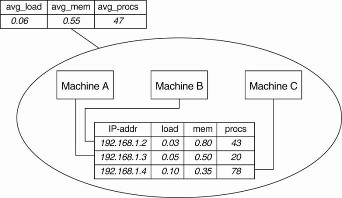
Fig. 2-17 shows how the information as gathered by each
machine can be viewed as a record in a database, and that these records jointly
form a relation (table). This representation is done on purpose: it is the way
that Astrolabe views all the collected data. However, per zone information can
only be computed from the basic records as maintained by hosts.
Aggregated information is obtained by programmable
aggregation functions, which are very similar to functions available in the
relational database language SQL. For example, assuming that the host
information from Fig. 2-17 is maintained in a local table called hostinfo, we
could collect the average number of processes for the zone containing machines
A, B, and C, through the simple SQL query
SELECT AVG(procs) AS avg_procs FROM hostinfo
Combined with a few enhancements to SQL, it is not hard to
imagine that more informative queries can be formulated.
Queries such as these are continuously evaluated by each
agent running on each host. Obviously, this is possible only if zone information
is propagated to all nodes that comprise Astrolabe. To this end, an agent
running on a host is responsible for computing parts of the tables of its
associated zones. Records for which it holds no computational responsibility
are occasionally sent to it through a simple, yet effective exchange procedure
known as gossiping. Gossiping protocols will be discussed in detail in Chap. 4.
Likewise, an agent will pass computed results to other agents as well.
[Page 63]
The result of this information exchange is that eventually,
all agents that needed to assist in obtaining some aggregated information will
see the same result (provided that no changes occur in the meantime).
2.4.3. Example:
Differentiating Replication Strategies in Globule
Let us now take a look at Globule, a collaborative content
distribution network (Pierre and van Steen, 2006). Globule relies on end-user
servers being placed in the Internet, and that these servers collaborate to
optimize performance through replication of Web pages. To this end, each origin
server (i.e., the server responsible for handling updates of a specific Web
site), keeps track of access patterns on a per-page basis. Access patterns are
expressed as read and write operations for a page, each operation being
timestamped and logged by the origin server for that page.
In its simplest form, Globule assumes that the Internet can
be viewed as an edge-server system as we explained before. In particular, it
assumes that requests can always be passed through an appropriate edge server,
as shown in Fig. 2-18. This simple model allows an origin server to see what
would have happened if it had placed a replica on a specific edge server. On
the one hand, placing a replica closer to clients would improve
client-perceived latency, but this will induce traffic between the origin
server and that edge server in order to keep a replica consistent with the
original page.
Figure 2-18. The edge-server model assumed by Globule.
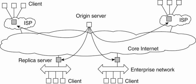
When an origin server receives a request for a page, it records
the IP address from where the request originated, and looks up the ISP or
enterprise network associated with that request using the WHOIS Internet
service (Deutsch et al., 1995). The origin server then looks for the nearest
existing replica server that could act as edge server for that client, and
subsequently computes the latency to that server along with the maximal
bandwidth. In its simplest configuration, Globule assumes that the latency
between the replica server and the requesting user machine is negligible, and
likewise that bandwidth between the two is plentiful.
[Page 64]
Once enough requests for a page have been collected, the
origin server performs a simple "what-if analysis." Such an analysis
boils down to evaluating several replication policies, where a policy describes
where a specific page is replicated to, and how that page is kept consistent.
Each replication policy incurs a cost that can be expressed as a simple linear
function:
cost=(w1xm1)+(w2xm2)+ . . .+(wnxmn)
where mk denotes a performance metric and wk is the weight
indicating how important that metric is. Typical performance metrics are the
aggregated delays between a client and a replica server when returning copies
of Web pages, the total consumed bandwidth between the origin server and a
replica server for keeping a replica consistent, and the number of stale copies
that are (allowed to be) returned to a client (Pierre et al., 2002).
For example, assume that the typical delay between the time
a client C issues a request and when that page is returned from the best
replica server is dC ms. Note that what the best replica server is, is
determined by a replication policy. Let m1 denote the aggregated delay over a
given time period, that is, m1=Σ dC. If the origin server wants to optimize
client-perceived latency, it will choose a relatively high value for w1. As a
consequence, only those policies that actually minimize m1 will show to have
relatively low costs.
In Globule, an origin server regularly evaluates a few tens
of replication polices using a trace-driven simulation, for each Web page
separately. From these simulations, a best policy is selected and subsequently
enforced. This may imply that new replicas are installed at different edge
servers, or that a different way of keeping replicas consistent is chosen. The
collecting of traces, the evaluation of replication policies, and the
enforcement of a selected policy is all done automatically.
There are a number of subtle issues that need to be dealt
with. For one thing, it is unclear how many requests need to be collected
before an evaluation of the current policy can take place. To explain, suppose
that at time Ti the origin server selects policy p for the next period until
Ti+1. This selection takes place based on a series of past requests that were
issued between Ti-1 and Ti. Of course, in hindsight at time Ti+1, the server
may come to the conclusion that it should have selected policy p* given the
actual requests that were issued between Ti and Ti+1. If p* is different from
p, then the selection of p at Ti was wrong.
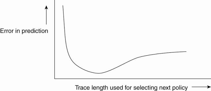
As it turns out, the percentage of wrong predictions is
dependent on the length of the series of requests (called the trace length)
that are used to predict and select a next policy. This dependency is sketched
in Fig. 2-19. What is seen is that the error in predicting the best policy goes
up if the trace is not long enough. This is easily explained by the fact that
we need enough requests to do a proper evaluation. However, the error also
increases if we use too many requests. The reason for this is that a very long
trace length captures so many changes in access patterns that predicting the
best policy to follow becomes difficult, if not impossible. This phenomenon is
well known and is analogous to trying to predict the weather for tomorrow by
looking at what happened during the immediately preceding 100 years. A much
better prediction can be made by just looking only at the recent past.
[Page 65]
Figure 2-19. The dependency between prediction accuracy and
trace length.
Finding the optimal trace length can be done automatically
as well. We leave it as an exercise to sketch a solution to this problem.
2.4.4. Example:
Automatic Component Repair Management in Jade
When maintaining clusters of computers, each running
sophisticated servers, it becomes important to alleviate management problems.
One approach that can be applied to servers that are built using a
component-based approach, is to detect component failures and have them
automatically replaced. The Jade system follows this approach (Bouchenak et
al., 2005). We describe it briefly in this section.
Jade is built on the Fractal component model, a Java
implementation of a framework that allows components to be added and removed at
runtime (Bruneton et al., 2004). A component in Fractal can have two types of
interfaces. A server interface is used to call methods that are implemented by
that component. A client interface is used by a component to call other
components. Components are connected to each other by binding interfaces. For
example, a client interface of component C1 can be bound to the server
interface of component C2. A primitive binding means that a call to a client
interface directly leads to calling the bounded server interface. In the case of
composite binding, the call may proceed through one or more other components,
for example, because the client and server interface did not match and some
kind of conversion is needed. Another reason may be that the connected
components lie on different machines.
[Page 66]
Jade uses the notion of a repair management domain. Such a
domain consists of a number of nodes, where each node represents a server along
with the components that are executed by that server. There is a separate node
manager which is responsible for adding and removing nodes from the domain. The
node manager may be replicated for assuring high availability.
Each node is equipped with failure detectors, which monitor
the health of a node or one of its components and report any failures to the
node manager. Typically, these detectors consider exceptional changes in the
state of component, the usage of resources, and the actual failure of a
component. Note that the latter may actually mean that a machine has crashed.
When a failure has been detected, a repair procedure is
started. Such a procedure is driven by a repair policy, partly executed by the
node manager. Policies are stated explicitly and are carried out depending on
the detected failure. For example, suppose a node failure has been detected. In
that case, the repair policy may prescribe that the following steps are to be
carried out:
1. Terminate every binding between a component on a nonfaulty node,
and a component on the node that just failed.
2. Request the node manager to start and add a new node to the
domain.
3. Configure the new node with exactly the same components as those
on the crashed node.
4. Re-establish all the bindings that were previously terminated.
In this example, the repair policy is simple and will only
work when no crucial data has been lost (the crashed components are said to be
stateless).
The approach followed by Jade is an example of
self-management: upon the detection of a failure, a repair policy is
automatically executed to bring the system as a whole into a state in which it
was before the crash. Being a component-based system, this automatic repair
requires specific support to allow components to be added and removed at
runtime. In general, turning legacy applications into self-managing systems is
not possible.