Chapter 2. Architectures
Distributed systems are
often complex pieces of software of which the components are by definition
dispersed across multiple machines. To master their complexity, it is crucial that
these systems are properly organized. There are different ways on how to view
the organization of a distributed system, but an obvious one is to make a
distinction between the logical organization of the collection of software
components and on the other hand the actual physical realization.
The organization of
distributed systems is mostly about the software components that constitute the
system. These software architectures tell us how the various software
components are to be organized and how they should interact. In this chapter we
will first pay attention to some commonly applied approaches toward organizing
(distributed) computer systems.
The actual realization of a
distributed system requires that we instantiate and place software components on
real machines. There are many different choices that can be made in doing so.
The final instantiation of a software architecture is also referred to as a
system architecture. In this chapter we will look into traditional centralized
architectures in which a single server implements most of the software
components (and thus functionality), while remote clients can access that
server using simple communication means. In addition, we consider decentralized
architectures in which machines more or less play equal roles, as well as
hybrid organizations.
As we explained in Chap. 1,
an important goal of distributed systems is to separate applications from
underlying platforms by providing a middleware layer. Adopting such a layer is
an important architectural decision, and its main purpose is to provide
distribution transparency. However, trade-offs need to be made to achieve
transparency, which has led to various techniques to make middleware adaptive.
We discuss some of the more commonly applied ones in this chapter, as they
affect the organization of the middleware itself.
[Page 34]
Adaptability in distributed
systems can also be achieved by having the system monitor its own behavior and
taking appropriate measures when needed. This insight has led to a class of
what are now referred to as autonomic systems. These distributed systems are
frequently organized in the form of feedback control loops, which form an
important architectural element during a system's design. In this chapter, we
devote a section to autonomic distributed systems.
2.1. Architectural Styles
We start our discussion on
architectures by first considering the logical organization of distributed
systems into software components, also referred to as software architecture
(Bass et al., 2003). Research on software architectures has matured
considerably and it is now commonly accepted that designing or adopting an
architecture is crucial for the successful development of large systems.
For our discussion, the
notion of an architectural style is important. Such a style is formulated in
terms of components, the way that components are connected to each other, the
data exchanged between components, and finally how these elements are jointly
configured into a system. A component is a modular unit with well-defined
required and provided interfaces that is replaceable within its environment
(OMG, 2004b). As we shall discuss below, the important issue about a component
for distributed systems is that it can be replaced, provided we respect its
interfaces. A somewhat more difficult concept to grasp is that of a connector,
which is generally described as a mechanism that mediates communication,
coordination, or cooperation among components (Mehta et al., 2000; and Shaw and
Clements, 1997). For example, a connector can be formed by the facilities for
(remote) procedure calls, message passing, or streaming data.
Using components and
connectors, we can come to various configurations, which, in turn have been
classified into architectural styles. Several styles have by now been
identified, of which the most important ones for distributed systems are:
- Layered architectures
- Object-based architectures
- Data-centered architectures
- Event-based architectures
The basic idea for the layered
style is simple: components are organized in a layered fashion where a
component at layer Li is allowed to call components at the underlying layer
Li-1, but not the other way around, as shown in Fig. 2-1(a). This model has
been widely adopted by the networking community; we briefly review it in Chap.
4. An key observation is that control generally flows from layer to layer:
requests go down the hierarchy whereas the results flow upward.
[Page 35]
Figure 2-1. The (a) layered
and (b) object-based architectural style.
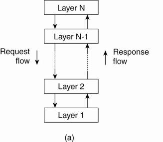
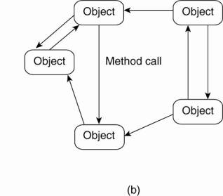
A far looser organization is
followed in object-based architectures, which are illustrated in Fig. 2-1(b).
In essence, each object corresponds to what we have defined as a component, and
these components are connected through a (remote) procedure call mechanism. Not
surprisingly, this software architecture matches the client-server system
architecture we described above. The layered and object-based architectures
still form the most important styles for large software systems (Bass et al.,
2003).
Data-centered architectures
evolve around the idea that processes communicate through a common (passive or
active) repository. It can be argued that for distributed systems these
architectures are as important as the layered and object-based architectures.
For example, a wealth of networked applications have been developed that rely
on a shared distributed file system in which virtually all communication takes
place through files. Likewise, Web-based distributed systems, which we discuss extensively
in Chap. 12, are largely data-centric: processes communicate through the use of
shared Web-based data services.
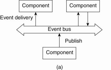
In event-based
architectures, processes essentially communicate through the propagation of
events, which optionally also carry data, as shown in Fig. 2-2(a). For
distributed systems, event propagation has generally been associated with what
are known as publish/subscribe systems (Eugster et al., 2003). The basic idea
is that processes publish events after which the middleware ensures that only
those processes that subscribed to those events will receive them. The main
advantage of event-based systems is that processes are loosely coupled. In
principle, they need not explicitly refer to each other. This is also referred
to as being decoupled in space, or referentially decoupled.
[Page 36]
Figure 2-2. The (a)
event-based and (b) shared data-space architectural style.
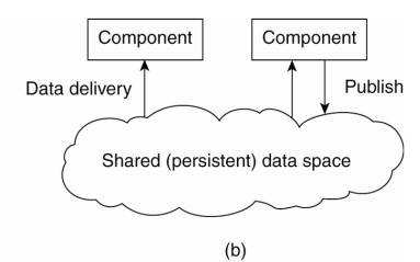
Event-based architectures
can be combined with data-centered architectures, yielding what is also known as
shared data spaces. The essence of shared data spaces is that processes are now
also decoupled in time: they need not both be active when communication takes
place. Furthermore, many shared data spaces use a SQL-like interface to the
shared repository in that sense that data can be accessed using a description
rather than an explicit reference, as is the case with files. We devote Chap.
13 to this architectural style.
What makes these software
architectures important for distributed systems is that they all aim at
achieving (at a reasonable level) distribution transparency. However, as we
have argued, distribution transparency requires making trade-offs between
performance, fault tolerance, ease-of-programming, and so on. As there is no
single solution that will meet the requirements for all possible distributed
applications, researchers have abandoned the idea that a single distributed
system can be used to cover 90% of all possible cases.
2.2. System Architectures
Now that we have briefly
discussed some common architectural styles, let us take a look at how many
distributed systems are actually organized by considering where software
components are placed. Deciding on software components, their interaction, and
their placement leads to an instance of a software architecture, also called a
system architecture (Bass et al., 2003). We will discuss centralized and
decentralized organizations, as well as various hybrid forms.
2.2.1. Centralized Architectures
Despite the lack of
consensus on many distributed systems issues, there is one issue that many
researchers and practitioners agree upon: thinking in terms of clients that
request services from servers helps us understand and manage the complexity of
distributed systems and that is a good thing.
[Page 37]
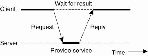
In the basic client-server
model, processes in a distributed system are divided into two (possibly
overlapping) groups. A server is a process implementing a specific service, for
example, a file system service or a database service. A client is a process
that requests a service from a server by sending it a request and subsequently
waiting for the server's reply. This client-server interaction, also known as
request-reply behavior is shown in Fig. 2-3
Figure 2-3. General
interaction between a client and a server.
Communication between a
client and a server can be implemented by means of a simple connectionless
protocol when the underlying network is fairly reliable as in many local-area
networks. In these cases, when a client requests a service, it simply packages
a message for the server, identifying the service it wants, along with the
necessary input data. The message is then sent to the server. The latter, in
turn, will always wait for an incoming request, subsequently process it, and
package the results in a reply message that is then sent to the client.
Using a connectionless
protocol has the obvious advantage of being efficient. As long as messages do
not get lost or corrupted, the request/reply protocol just sketched works fine.
Unfortunately, making the protocol resistant to occasional transmission
failures is not trivial. The only thing we can do is possibly let the client
resend the request when no reply message comes in. The problem, however, is
that the client cannot detect whether the original request message was lost, or
that transmission of the reply failed. If the reply was lost, then resending a
request may result in performing the operation twice. If the operation was
something like "transfer $10,000 from my bank account," then clearly,
it would have been better that we simply reported an error instead. On the
other hand, if the operation was "tell me how much money I have
left," it would be perfectly acceptable to resend the request. When an
operation can be repeated multiple times without harm, it is said to be
idempotent. Since some requests are idempotent and others are not it should be
clear that there is no single solution for dealing with lost messages. We defer
a detailed discussion on handling transmission failures to Chap. 8.
As an alternative, many
client-server systems use a reliable connection-oriented protocol. Although
this solution is not entirely appropriate in a local-area network due to
relatively low performance, it works perfectly fine in wide-area systems in
which communication is inherently unreliable. For example, virtually all
Internet application protocols are based on reliable TCP/IP connections. In
this case, whenever a client requests a service, it first sets up a connection
to the server before sending the request. The server generally uses that same
connection to send the reply message, after which the connection is torn down.
The trouble is that setting up and tearing down a connection is relatively
costly, especially when the request and reply messages are small.
[Page 38]
Application Layering
The client-server model has
been subject to many debates and controversies over the years. One of the main
issues was how to draw a clear distinction between a client and a server. Not surprisingly,
there is often no clear distinction. For example, a server for a distributed
database may continuously act as a client because it is forwarding requests to
different file servers responsible for implementing the database tables. In
such a case, the database server itself essentially does no more than process
queries.
However, considering that
many client-server applications are targeted toward supporting user access to
databases, many people have advocated a distinction between the following three
levels, essentially following the layered architectural style we discussed
previously:
- The user-interface level
- The processing level
- The data level
The user-interface level
contains all that is necessary to directly interface with the user, such as
display management. The processing level typically contains the applications.
The data level manages the actual data that is being acted on.
Clients typically implement
the user-interface level. This level consists of the programs that allow end
users to interact with applications. There is a considerable difference in how
sophisticated user-interface programs are.
The simplest user-interface
program is nothing more than a character-based screen. Such an interface has
been typically used in mainframe environments. In those cases where the
mainframe controls all interaction, including the keyboard and monitor, one can
hardly speak of a client-server environment. However, in many cases, the user's
terminal does some local processing such as echoing typed keystrokes, or
supporting form-like interfaces in which a complete entry is to be edited
before sending it to the main computer.
Nowadays, even in mainframe
environments, we see more advanced user interfaces. Typically, the client
machine offers at least a graphical display in which pop-up or pull-down menus
are used, and of which many of the screen controls are handled through a mouse
instead of the keyboard. Typical examples of such interfaces include the
X-Windows interfaces as used in many UNIX environments, and earlier interfaces
developed for MS-DOS PCs and Apple Macintoshes.
[Page 39]
Modern user interfaces offer
considerably more functionality by allowing applications to share a single
graphical window, and to use that window to exchange data through user actions.
For example, to delete a file, it is usually possible to move the icon
representing that file to an icon representing a trash can. Likewise, many word
processors allow a user to move text in a document to another position by using
only the mouse. We return to user interfaces in Chap. 3.
Many client-server
applications can be constructed from roughly three different pieces: a part
that handles interaction with a user, a part that operates on a database or
file system, and a middle part that generally contains the core functionality
of an application. This middle part is logically placed at the processing
level. In contrast to user interfaces and databases, there are not many aspects
common to the processing level. Therefore, we shall give several examples to
make this level clearer.
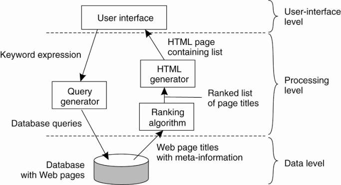
As a first example, consider
an Internet search engine. Ignoring all the animated banners, images, and other
fancy window dressing, the user interface of a search engine is very simple: a
user types in a string of keywords and is subsequently presented with a list of
titles of Web pages. The back end is formed by a huge database of Web pages
that have been prefetched and indexed. The core of the search engine is a
program that transforms the user's string of keywords into one or more database
queries. It subsequently ranks the results into a list, and transforms that
list into a series of HTML pages. Within the client-server model, this
information retrieval part is typically placed at the processing level. Fig. 2-4
shows this organization.
Figure 2-4. The simplified
organization of an Internet search engine into three different layers.
As a second example,
consider a decision support system for a stock brokerage. Analogous to a search
engine, such a system can be divided into a front end implementing the user
interface, a back end for accessing a database with the financial data, and the
analysis programs between these two. Analysis of financial data may require
sophisticated methods and techniques from statistics and artificial
intelligence. In some cases, the core of a financial decision support system
may even need to be executed on high-performance computers in order to achieve
the throughput and responsiveness that is expected from its users.
[Page 40]
As a last example, consider
a typical desktop package, consisting of a word processor, a spreadsheet
application, communication facilities, and so on. Such "office"
suites are generally integrated through a common user interface that supports
compound documents, and operates on files from the user's home directory. (In
an office environment, this home directory is often placed on a remote file
server.) In this example, the processing level consists of a relatively large
collection of programs, each having rather simple processing capabilities.
The data level in the
client-server model contains the programs that maintain the actual data on
which the applications operate. An important property of this level is that
data are often persistent, that is, even if no application is running, data
will be stored somewhere for next use. In its simplest form, the data level
consists of a file system, but it is more common to use a full-fledged
database. In the client-server model, the data level is typically implemented
at the server side.
Besides merely storing data,
the data level is generally also responsible for keeping data consistent across
different applications. When databases are being used, maintaining consistency
means that metadata such as table descriptions, entry constraints and
application-specific metadata are also stored at this level. For example, in
the case of a bank, we may want to generate a notification when a customer's
credit card debt reaches a certain value. This type of information can be
maintained through a database trigger that activates a handler for that trigger
at the appropriate moment.
In most business-oriented
environments, the data level is organized as a relational database. Data
independence is crucial here. The data are organized independent of the
applications in such a way that changes in that organization do not affect
applications, and neither do the applications affect the data organization.
Using relational databases in the client-server model helps separate the
processing level from the data level, as processing and data are considered
independent.
However, relational
databases are not always the ideal choice. A characteristic feature of many
applications is that they operate on complex data types that are more easily
modeled in terms of objects than in terms of relations. Examples of such data
types range from simple polygons and circles to representations of aircraft
designs, as is the case with computer-aided design (CAD) systems.
In those cases where data operations
are more easily expressed in terms of object manipulations, it makes sense to
implement the data level by means of an object-oriented or object-relational
database. Notably the latter type has gained popularity as these databases
build upon the widely dispersed relational data model, while offering the
advantages that object-orientation gives.
[Page 41]
Multitiered Architectures
The distinction into three
logical levels as discussed so far, suggests a number of possibilities for
physically distributing a client-server application across several machines.
The simplest organization is to have only two types of machines:
A client machine containing
only the programs implementing (part of) the user-interface level
A server machine containing
the rest, that is the programs implementing the processing and data level
In this organization
everything is handled by the server while the client is essentially no more
than a dumb terminal, possibly with a pretty graphical interface. There are many
other possibilities, of which we explore some of the more common ones in this
section.
One approach for organizing
the clients and servers is to distribute the programs in the application layers
of the previous section across different machines, as shown in Fig. 2-5 [see
also Umar (1997); and Jing et al. (1999)]. As a first step, we make a
distinction between only two kinds of machines: client machines and server
machines, leading to what is also referred to as a (physically) two-tiered
architecture.
Figure 2-5. Alternative
client-server organizations (a)–(e).
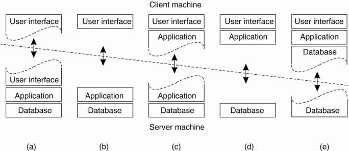
One possible organization is
to have only the terminal-dependent part of the user interface on the client
machine, as shown in Fig. 2-5(a), and give the applications remote control over
the presentation of their data. An alternative is to place the entire
user-interface software on the client side, as shown in Fig. 2-5(b). In such
cases, we essentially divide the application into a graphical front end, which
communicates with the rest of the application (residing at the server) through
an application-specific protocol. In this model, the front end (the client
software) does no processing other than necessary for presenting the
application's interface.
[Page 42]
Continuing along this line of
reasoning, we may also move part of the application to the front end, as shown
in Fig. 2-5(c). An example where this makes sense is where the application
makes use of a form that needs to be filled in entirely before it can be
processed. The front end can then check the correctness and consistency of the
form, and where necessary interact with the user. Another example of the
organization of Fig. 2-5(c), is that of a word processor in which the basic
editing functions execute on the client side where they operate on locally
cached, or in-memory data, but where the advanced support tools such as
checking the spelling and grammar execute on the server side.
In many client-server
environments, the organizations shown in Fig. 2-5(d) and Fig. 2-5(e) are particularly
popular. These organizations are used where the client machine is a PC or
workstation, connected through a network to a distributed file system or
database. Essentially, most of the application is running on the client
machine, but all operations on files or database entries go to the server. For
example, many banking applications run on an end-user's machine where the user
prepares transactions and such. Once finished, the application contacts the
database on the bank's server and uploads the transactions for further
processing. Fig. 2-5(e) represents the situation where the client's local disk
contains part of the data. For example, when browsing the Web, a client can
gradually build a huge cache on local disk of most recent inspected Web pages.
We note that for a few years
there has been a strong trend to move away from the configurations shown in
Fig. 2-5(d) and Fig. 2-5(e) in those case that client software is placed at
end-user machines. In these cases, most of the processing and data storage is
handled at the server side. The reason for this is simple: although client
machines do a lot, they are also more problematic to manage. Having more
functionality on the client machine makes client-side software more prone to
errors and more dependent on the client's underlying platform (i.e., operating
system and resources). From a system's management perspective, having what are
called fat clients is not optimal. Instead the thin clients as represented by
the organizations shown in Fig. 2-5(a)–(c) are much easier, perhaps at the cost
of less sophisticated user interfaces and client-perceived performance.
Note that this trend does
not imply that we no longer need distributed systems. On the contrary, what we
are seeing is that server-side solutions are becoming increasingly more
distributed as a single server is being replaced by multiple servers running on
different machines. In particular, when distinguishing only client and server
machines as we have done so far, we miss the point that a server may sometimes
need to act as a client, as shown in Fig. 2-6, leading to a (physically)
three-tiered architecture.
Figure 2-6. An example of a
server acting as client.
(This item is displayed on
page 43 in the print version)
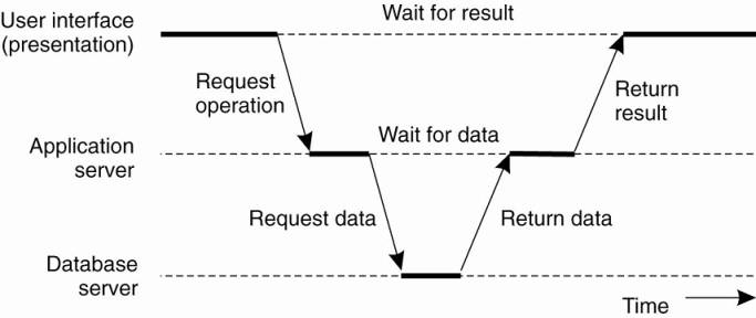
In this architecture, programs
that form part of the processing level reside on a separate server, but may
additionally be partly distributed across the client and server machines. A
typical example of where a three-tiered architecture is used is in transaction
processing. As we discussed in Chap. 1, a separate process, called the
transaction processing monitor, coordinates all transactions across possibly
different data servers.
[Page 43]
Another, but very different
example where we often see a three-tiered architecture is in the organization
of Web sites. In this case, a Web server acts as an entry point to a site,
passing requests to an application server where the actual processing takes
place. This application server, in turn, interacts with a database server. For
example, an application server may be responsible for running the code to
inspect the available inventory of some goods as offered by an electronic
bookstore. To do so, it may need to interact with a database containing the raw
inventory data. We will come back to Web site organization in Chap. 12.
2.2.2. Decentralized Architectures
Multitiered client-server
architectures are a direct consequence of dividing applications into a
user-interface, processing components, and a data level. The different tiers
correspond directly with the logical organization of applications. In many
business environments, distributed processing is equivalent to organizing a
client-server application as a multitiered architecture. We refer to this type
of distribution as vertical distribution. The characteristic feature of
vertical distribution is that it is achieved by placing logically different
components on different machines. The term is related to the concept of
vertical fragmentation as used in distributed relational databases, where it
means that tables are split column-wise, and subsequently distributed across
multiple machines (Oszu and Valduriez, 1999).
Again, from a system
management perspective, having a vertical distribution can help: functions are
logically and physically split across multiple machines, where each machine is
tailored to a specific group of functions. However, vertical distribution is
only one way of organizing client-server applications. In modern architectures,
it is often the distribution of the clients and the servers that counts, which
we refer to as horizontal distribution. In this type of distribution, a client
or server may be physically split up into logically equivalent parts, but each
part is operating on its own share of the complete data set, thus balancing the
load. In this section we will take a look at a class of modern system
architectures that support horizontal distribution, known as peer-to-peer
systems.
[Page 44]
From a high-level
perspective, the processes that constitute a peer-to-peer system are all equal.
This means that the functions that need to be carried out are represented by
every process that constitutes the distributed system. As a consequence, much
of the interaction between processes is symmetric: each process will act as a client
and a server at the same time (which is also referred to as acting as a
servent).
Given this symmetric
behavior, peer-to-peer architectures evolve around the question how to organize
the processes in an overlay network, that is, a network in which the nodes are
formed by the processes and the links represent the possible communication
channels (which are usually realized as TCP connections). In general, a process
cannot communicate directly with an arbitrary other process, but is required to
send messages through the available communication channels. Two types of
overlay networks exist: those that are structured and those that are not. These
two types are surveyed extensively in Lua et al. (2005) along with numerous
examples. Aberer et al. (2005) provide a reference architecture that allows for
a more formal comparison of the different types of peer-to-peer systems. A
survey taken from the perspective of content distribution is provided by
Androutsellis-Theotokis and Spinellis (2004).
Structured Peer-to-Peer Architectures
In a structured peer-to-peer
architecture, the overlay network is constructed using a deterministic
procedure. By far the most-used procedure is to organize the processes through
a distributed hash table (DHT). In a DHT-based system, data items are assigned
a random key from a large identifier space, such as a 128-bit or 160-bit
identifier. Likewise, nodes in the system are also assigned a random number
from the same identifier space. The crux of every DHT-based system is then to
implement an efficient and deterministic scheme that uniquely maps the key of a
data item to the identifier of a node based on some distance metric
(Balakrishnan, 2003). Most importantly, when looking up a data item, the
network address of the node responsible for that data item is returned.
Effectively, this is accomplished by routing a request for a data item to the
responsible node.
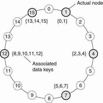
For example, in the Chord
system (Stoica et al., 2003) the nodes are logically organized in a ring such
that a data item with key k is mapped to the node with the smallest identifier
idk. This node is referred to as the successor of key k and denoted as succ(k),
as shown in Fig. 2-7. To actually look up the data item, an application running
on an arbitrary node would then call the function LOOKUP(k) which would
subsequently return the network address of succ(k). At that point, the
application can contact the node to obtain a copy of the data item.
[Page 45]
Figure 2-7. The mapping of
data items onto nodes in Chord.
We will not go into
algorithms for looking up a key now, but defer that discussion until Chap. 5
where we describe details of various naming systems. Instead, let us
concentrate on how nodes organize themselves into an overlay network, or, in
other words, membership management. In the following, it is important to
realize that looking up a key does not follow the logical organization of nodes
in the ring from Fig. 2-7. Rather, each node will maintain shortcuts to other
nodes in such a way that lookups can generally be done in Ο(log (N))
number of steps, where N is the number of nodes participating in the overlay.
Now consider Chord again.
When a node wants to join the system, it starts with generating a random identifier
id. Note that if the identifier space is large enough, then provided the random
number generator is of good quality, the probability of generating an
identifier that is already assigned to an actual node is close to zero. Then,
the node can simply do a lookup on id, which will return the network address of
succ(id). At that point, the joining node can simply contact succ(id) and its
predecessor and insert itself in the ring. Of course, this scheme requires that
each node also stores information on its predecessor. Insertion also yields
that each data item whose key is now associated with node id, is transferred
from succ(id).
Leaving is just as simple:
node id informs its departure to its predecessor and successor, and transfers
its data items to succ(id).
Similar approaches are
followed in other DHT-based systems. As an example, consider the Content
Addressable Network (CAN), described in Ratnasamy et al. (2001). CAN deploys a
d-dimensional Cartesian coordinate space, which is completely partitioned among
all all the nodes that participate in the system. For purpose of illustration,
let us consider only the 2-dimensional case, of which an example is shown in
Fig. 2-8.
[Page 46]
Figure 2-8. (a) The mapping
of data items onto nodes in CAN. (b) Splitting a region when a node joins.
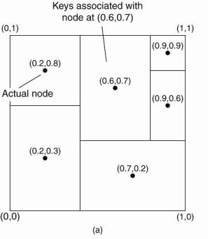
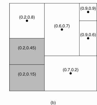
Fig. 2-8(a) shows how the
two-dimensional space [0,1]x[0,1] is divided among six nodes. Each node has an
associated region. Every data item in CAN will be assigned a unique point in
this space, after which it is also clear which node is responsible for that
data (ignoring data items that fall on the border of multiple regions, for
which a deterministic assignment rule is used).
When a node P wants to join
a CAN system, it picks an arbitrary point from the coordinate space and
subsequently looks up the node Q in whose region that point falls. This lookup
is accomplished through positioned-based routing, of which the details are
deferred until later chapters. Node Q then splits its region into two halves,
as shown in Fig. 2-8(b), and one half is assigned to the node P. Nodes keep
track of their neighbors, that is, nodes responsible for adjacent region. When
splitting a region, the joining node P can easily come to know who its new
neighbors are by asking node P. As in Chord, the data items for which node P is
now responsible are transferred from node Q.
Leaving is a bit more
problematic in CAN. Assume that in Fig. 2-8, the node with coordinate (0.6,0.7)
leaves. Its region will be assigned to one of its neighbors, say the node at
(0.9,0.9), but it is clear that simply merging it and obtaining a rectangle
cannot be done. In this case, the node at (0.9,0.9) will simply take care of
that region and inform the old neighbors of this fact. Obviously, this may lead
to less symmetric partitioning of the coordinate space, for which reason a
background process is periodically started to repartition the entire space.
[Page 47]
Unstructured Peer-to-Peer Architectures
Unstructured peer-to-peer
systems largely rely on randomized algorithms for constructing an overlay
network. The main idea is that each node maintains a list of neighbors, but
that this list is constructed in a more or less random way. Likewise, data
items are assumed to be randomly placed on nodes. As a consequence, when a node
needs to locate a specific data item, the only thing it can effectively do is
flood the network with a search query (Risson and Moors, 2006). We will return
to searching in unstructured overlay networks in Chap. 5, and for now
concentrate on membership management.
One of the goals of many
unstructured peer-to-peer systems is to construct an overlay network that
resembles a random graph. The basic model is that each node maintains a list of
c neighbors, where, ideally, each of these neighbors represents a randomly
chosen live node from the current set of nodes. The list of neighbors is also
referred to as a partial view. There are many ways to construct such a partial
view. Jelasity et al. (2004, 2005a) have developed a framework that captures many
different algorithms for overlay construction to allow for evaluations and
comparison. In this framework, it is assumed that nodes regularly exchange
entries from their partial view. Each entry identifies another node in the
network, and has an associated age that indicates how old the reference to that
node is. Two threads are used, as shown in Fig. 2-9.
The active thread takes the
initiative to communicate with another node. It selects that node from its
current partial view. Assuming that entries need to be pushed to the selected
peer, it continues by constructing a buffer containing c/2+1 entries, including
an entry identifying itself. The other entries are taken from the current
partial view.
If the node is also in pull
mode it will wait for a response from the selected peer. That peer, in the
meantime, will also have constructed a buffer by means the passive thread shown
in Fig. 2-9(b), whose activities strongly resemble that of the active thread.
The crucial point is the construction
of a new partial view. This view, for initiating as well as for the contacted
peer, will contain exactly c entries, part of which will come from received
buffer. In essence, there are two ways to construct the new view. First, the
two nodes may decide to discard the entries that they had sent to each other.
Effectively, this means that they will swap part of their original views. The
second approach is to discard as many old entries as possible. In general, it
turns out that the two approaches are complementary [see Jelasity et al.
(2005a) for the details]. It turns out that many membership management
protocols for unstructured overlays fit this framework. There are a number of
interesting observations to make.
First, let us assume that
when a node wants to join it contacts an arbitrary other node, possibly from a
list of well-known access points. This access point is just a regular member of
the overlay, except that we can assume it to be highly available. In this case,
it turns out that protocols that use only push mode or only pull mode can
fairly easily lead to disconnected overlays. In other words, groups of nodes
will become isolated and will never be able to reach every other node in the
network. Clearly, this is an undesirable feature, for which reason it makes
more sense to let nodes actually exchange entries.
[Page 48]
Figure 2-9. (a) The steps
taken by the active thread. (b) The steps take by the passive thread.
|
Actions by active
thread (periodically repeated): select a peer P from the current partial
view; if PUSH_MODE { mybuffer = [(MyAddress, 0)]; permute partial view; move H oldest entries to the end; append first c/2 entries to mybuffer; send mybuffer to P; } else { send trigger to P; } if PULL_MODE { receive P's buffer; } construct a new partial view from the
current one and P's buffer; increment the age of every entry in the
new partial view; (a) Actions by passive
thread: receive buffer from any process Q; if PULL_MODE { mybuffer = [(MyAddress, 0)]; permute partial vie w; move H oldest entries to the end; append first c/2 entries to mybuffer; send mybuffer to P; } construct a new partial view from the
current one and P's buffer; increment the age of every entry in the
new partial view; (b) |
Second, leaving the network turns
out to be a very simple operation provided the nodes exchange partial views on
a regular basis. In this case, a node can simply depart without informing any
other node. What will happen is that when a node P selects one of its apparent
neighbors, say node Q, and discovers that Q no longer responds, it simply
removes the entry from its partial view to select another peer. It turns out
that when constructing a new partial view, a node follows the policy to discard
as many old entries as possible, departed nodes will rapidly be forgotten. In
other words, entries referring to departed nodes will automatically be quickly
removed from partial views.
[Page 49]
However, there is a price to
pay when this strategy is followed. To explain, consider for a node P the set
of nodes that have an entry in their partial view that refers to P.
Technically, this is known as the indegree of a node. The higher node P's
indegree is, the higher the probability that some other node will decide to
contact P. In other words, there is a danger that P will become a popular node,
which could easily bring it into an imbalanced position regarding workload.
Systematically discarding old entries turns out to promote nodes to ones having
a high indegree. There are other trade-offs in addition, for which we refer to
Jelasity et al. (2005a).
Topology Management of
Overlay Networks
Although it would seem that
structured and unstructured peer-to-peer systems form strict independent
classes, this need actually not be case [see also Castro et al. (2005)]. One
key observation is that by carefully exchanging and selecting entries from
partial views, it is possible to construct and maintain specific topologies of
overlay networks. This topology management is achieved by adopting a
two-layered approach, as shown in Fig. 2-10.
Figure 2-10. A two-layered
approach for constructing and maintaining specific overlay topologies using
techniques from unstructured peer-to-peer systems.
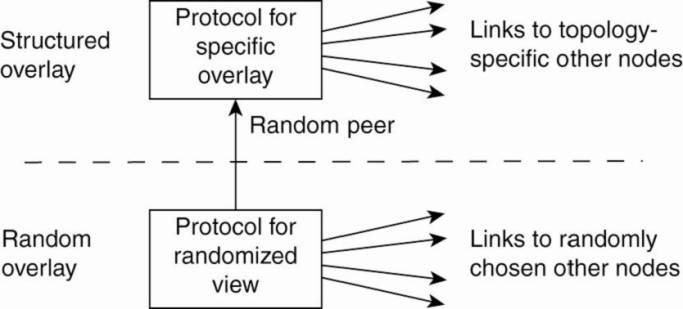
The lowest layer constitutes
an unstructured peer-to-peer system in which nodes periodically exchange
entries of their partial views with the aim to maintain an accurate random
graph. Accuracy in this case refers to the fact that the partial view should be
filled with entries referring to randomly selected live nodes.
The lowest layer passes its
partial view to the higher layer, where an additional selection of entries
takes place. This then leads to a second list of neighbors corresponding to the
desired topology. Jelasity and Babaoglu (2005) propose to use a ranking function
by which nodes are ordered according to some criterion relative to a given
node. A simple ranking function is to order a set of nodes by increasing
distance from a given node P. In that case, node P will gradually build up a
list of its nearest neighbors, provided the lowest layer continues to pass
randomly selected nodes.
[Page 50]
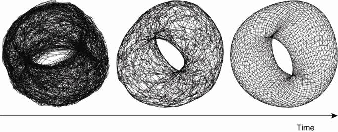
As an illustration, consider
a logical grid of size NxN with a node placed on each point of the grid. Every
node is required to maintain a list of c nearest neighbors, where the distance
between a node at (a1, a2) and (b1, b2) is defined as d1+d2, with di=min (N-|
ai-bi|,|ai-bi|). If the lowest layer periodically executes the protocol as
outlined in Fig. 2-9, the topology that will evolve is a torus, shown in Fig.
2-11.
Figure 2-11. Generating a
specific overlay network using a two-layered unstructured peer-to-peer system
[adapted with permission from Jelasity and Babaoglu (2005)].
Of course, completely
different ranking functions can be used. Notably those that are related to
capturing the semantic proximity of the data items as stored at a peer node are
interesting. This proximity allows for the construction of semantic overlay
networks that allow for highly efficient search algorithms in unstructured
peer-to-peer systems. We will return to these systems in Chap. 5 when we
discuss attribute-based naming.
Superpeers
Notably in unstructured
peer-to-peer systems, locating relevant data items can become problematic as
the network grows. The reason for this scalability problem is simple: as there
is no deterministic way of routing a lookup request to a specific data item,
essentially the only technique a node can resort to is flooding the request.
There are various ways in which flooding can be dammed, as we will discuss in
Chap. 5, but as an alternative many peer-to-peer systems have proposed to make
use of special nodes that maintain an index of data items.
There are other situations
in which abandoning the symmetric nature of peer-to-peer systems is sensible.
Consider a collaboration of nodes that offer resources to each other. For
example, in a collaborative content delivery network (CDN), nodes may offer
storage for hosting copies of Web pages allowing Web clients to access pages
nearby, and thus to access them quickly. In this case a node P may need to seek
for resources in a specific part of the network. In that case, making use of a
broker that collects resource usage for a number of nodes that are in each
other's proximity will allow to quickly select a node with sufficient
resources.
[Page 51]
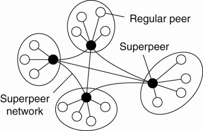
Nodes such as those
maintaining an index or acting as a broker are generally referred to as
superpeers. As their name suggests, superpeers are often also organized in a
peer-to-peer network, leading to a hierarchical organization as explained in
Yang and Garcia-Molina (2003). A simple example of such an organization is
shown in Fig. 2-12. In this organization, every regular peer is connected as a
client to a superpeer. All communication from and to a regular peer proceeds through
that peer's associated superpeer.
Figure 2-12. A hierarchical
organization of nodes into a superpeer network.
In many cases, the
client-superpeer relation is fixed: whenever a regular peer joins the network,
it attaches to one of the superpeers and remains attached until it leaves the
network. Obviously, it is expected that superpeers are long-lived processes
with a high availability. To compensate for potential unstable behavior of a
superpeer, backup schemes can be deployed, such as pairing every superpeer with
another one and requiring clients to attach to both.
Having a fixed association
with a superpeer may not always be the best solution. For example, in the case
of file-sharing networks, it may be better for a client to attach to a superpeer
that maintains an index of files that the client is generally interested in. In
that case, chances are bigger that when a client is looking for a specific
file, its superpeer will know where to find it. Garbacki et al. (2005) describe
a relatively simple scheme in which the client-superpeer relation can change as
clients discover better superpeers to associate with. In particular, a
superpeer returning the result of a lookup operation is given preference over
other superpeers.
As we have seen, peer-to-peer
networks offer a flexible means for nodes to join and leave the network.
However, with superpeer networks a new problem is introduced, namely how to
select the nodes that are eligible to become superpeer. This problem is closely
related to the leader-election problem, which we discuss in Chap. 6, when we
return to electing superpeers in a peer-to-peer network.
[Page 52]
2.2.3. Hybrid Architectures
So far, we have focused on
client-server architectures and a number of peer-to-peer architectures. Many
distributed systems combine architectural features, as we already came across
in superpeer networks. In this section we take a look at some specific classes
of distributed systems in which client-server solutions are combined with
decentralized architectures.
Edge-Server Systems
An important class of
distributed systems that is organized according to a hybrid architecture is
formed by edge-server systems. These systems are deployed on the Internet where
servers are placed "at the edge" of the network. This edge is formed
by the boundary between enterprise networks and the actual Internet, for
example, as provided by an Internet Service Provider (ISP). Likewise, where end
users at home connect to the Internet through their ISP, the ISP can be
considered as residing at the edge of the Internet. This leads to a general
organization as shown in Fig. 2-13.
Figure 2-13. Viewing the
Internet as consisting of a collection of edge servers.
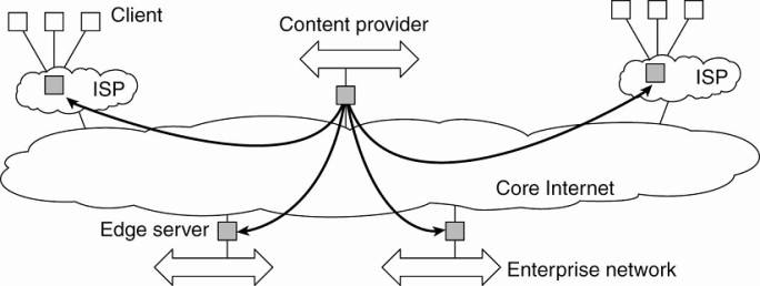
End users, or clients in
general, connect to the Internet by means of an edge server. The edge server's
main purpose is to serve content, possibly after applying filtering and
transcoding functions. More interesting is the fact that a collection of edge
servers can be used to optimize content and application distribution. The basic
model is that for a specific organization, one edge server acts as an origin
server from which all content originates. That server can use other edge
servers for replicating Web pages and such (Leff et al., 2004; Nayate et al.,
2004; and Rabinovich and Spatscheck, 2002). We will return to edge-server
systems in Chap. 12 when we discuss Web-based solutions.
[Page 53]
Collaborative Distributed Systems
Hybrid structures are
notably deployed in collaborative distributed systems. The main issue in many
of these systems to first get started, for which often a traditional
client-server scheme is deployed. Once a node has joined the system, it can use
a fully decentralized scheme for collaboration.
To make matters concrete,
let us first consider the BitTorrent file-sharing system (Cohen, 2003).
BitTorrent is a peer-to-peer file downloading system. Its principal working is
shown in Fig. 2-14 The basic idea is that when an end user is looking for a
file, he downloads chunks of the file from other users until the downloaded
chunks can be assembled together yielding the complete file. An important
design goal was to ensure collaboration. In most file-sharing systems, a
significant fraction of participants merely download files but otherwise
contribute close to nothing (Adar and Huberman, 2000; Saroiu et al., 2003; and
Yang et al., 2005). To this end, a file can be downloaded only when the
downloading client is providing content to someone else. We will return to this
"tit-for-tat" behavior shortly.
Figure 2-14. The principal
working of BitTorrent [adapted with permission from Pouwelse et al. (2004)].
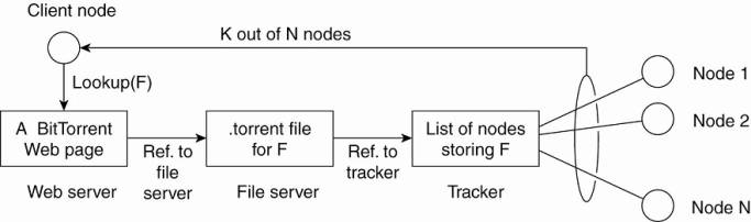
To download a file, a user
needs to access a global directory, which is just one of a few well-known Web sites.
Such a directory contains references to what are called .torrent files. A
.torrent file contains the information that is needed to download a specific
file. In particular, it refers to what is known as a tracker, which is a server
that is keeping an accurate account of active nodes that have (chunks) of the
requested file. An active node is one that is currently downloading another
file. Obviously, there will be many different trackers, although there will
generally be only a single tracker per file (or collection of files).
Once the nodes have been
identified from where chunks can be downloaded, the downloading node
effectively becomes active. At that point, it will be forced to help others,
for example by providing chunks of the file it is downloading that others do
not yet have. This enforcement comes from a very simple rule: if node P notices
that node Q is downloading more than it is uploading, P can decide to decrease
the rate at which it sends data to Q. This scheme works well provided P has something
to download from Q. For this reason, nodes are often supplied with references
to many other nodes putting them in a better position to trade data.
[Page 54]
Clearly, BitTorrent combines
centralized with decentralized solutions. As it turns out, the bottleneck of
the system is, not surprisingly, formed by the trackers.
As another example, consider
the Globule collaborative content distribution network (Pierre and van Steen,
2006). Globule strongly resembles the edge-server architecture mentioned above.
In this case, instead of edge servers, end users (but also organizations)
voluntarily provide enhanced Web servers that are capable of collaborating in
the replication of Web pages. In its simplest form, each such server has the
following components:
- A component that can redirect client requests to
other servers.
- A component for analyzing access patterns.
- A component for managing the replication of Web
pages.
The server provided by Alice
is the Web server that normally handles the traffic for Alice's Web site and is
called the origin server for that site. It collaborates with other servers, for
example, the one provided by Bob, to host the pages from Bob's site. In this
sense, Globule is a decentralized distributed system. Requests for Alice's Web
site are initially forwarded to her server, at which point they may be
redirected to one of the other servers. Distributed redirection is also
supported.
However, Globule also has a
centralized component in the form of its broker. The broker is responsible for
registering servers, and making these servers known to others. Servers
communicate with the broker completely analogous to what one would expect in a
client-server system. For reasons of availability, the broker can be
replicated, but as we shall later in this book, this type of replication is
widely applied in order to achieve reliable client-server computing.
2.3. Architectures Versus Middleware
When considering the
architectural issues we have discussed so far, a question that comes to mind is
where middleware fits in. As we discussed in Chap. 1, middleware forms a layer
between applications and distributed platforms, as shown in Fig. 1-1. An
important purpose is to provide a degree of distribution transparency, that is,
to a certain extent hiding the distribution of data, processing, and control
from applications.
What is comonly seen in
practice is that middleware systems actually follow a specific architectural
sytle. For example, many middleware solutions have adopted an object-based
architectural style, such as CORBA (OMG, 2004a). Others, like TIB/Rendezvous
(TIBCO, 2005) provide middleware that follows the event-based architectural
style. In later chapters, we will come across more examples of architectural
styles.
[Page 55]
Having middleware molded
according to a specific architectural style has the benefit that designing
applications may become simpler. However, an obvious drawback is that the
middleware may no longer be optimal for what an application developer had in
mind. For example, CORBA initially offered only objects that could be invoked
by remote clients. Later, it was felt that having only this form of interaction
was too restrictive, so that other interaction patterns such as messaging were
added. Obviously, adding new features can easily lead to bloated middle-ware
solutions.
In addition, although
middleware is meant to provide distribution transparency, it is generally felt
that specific solutions should be adaptable to application requirements. One
solution to this problem is to make several versions of a middleware system,
where each version is tailored to a specific class of applications. An approach
that is generally considered better is to make middleware systems such that
they are easy to configure, adapt, and customize as needed by an application.
As a result, systems are now being developed in which a stricter separation
between policies and mechanisms is being made. This has led to several
mechanisms by which the behavior of middleware can be modified (Sadjadi and
McKinley, 2003). Let us take a look at some of the commonly followed
approaches.
2.3.1. Interceptors
Conceptually, an interceptor
is nothing but a software construct that will break the usual flow of control
and allow other (application specific) code to be executed. To make
interceptors generic may require a substantial implementation effort, as
illustrated in Schmidt et al. (2000), and it is unclear whether in such cases
generality should be preferred over restricted applicability and simplicity.
Also, in many cases having only limited interception facilities will improve
management of the software and the distributed system as a whole.
To make matters concrete,
consider interception as supported in many object-based distributed systems.
The basic idea is simple: an object A can call a method that belongs to an
object B, while the latter resides on a different machine than A. As we explain
in detail later in the book, such a remote-object invocation is carried as a
three-step approach:
1. Object A is offered a local interface
that is exactly the same as the interface offered by object B. A simply calls
the method available in that interface.
2. The call by A is transformed into a
generic object invocation, made possible through a general object-invocation
interface offered by the middleware at the machine where A resides.
3. Finally, the generic object invocation
is transformed into a message that is sent through the transport-level network
interface as offered by A's local operating system.
Figure 2-15. Using
interceptors to handle remote-object invocations.
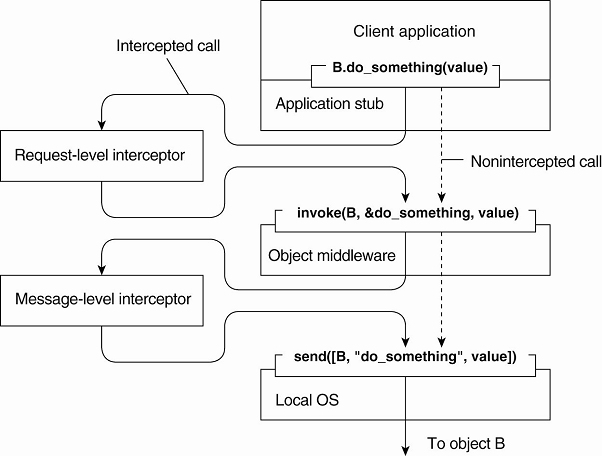
After the first step, the
call B.do_something(value) is transformed into a generic call such as invoke(B,
&do_something, value) with a reference to B's method and the parameters
that go along with the call. Now imagine that object B is replicated. In that
case, each replica should actually be invoked. This is a clear point where
interception can help. What the request-level interceptor will do is simply
call invoke(B, &do_something, value) for each of the replicas. The beauty
of this all is that the object A need not be aware of the replication of B, but
also the object middleware need not have special components that deal with this
replicated call. Only the request-level interceptor, which may be added to the
middleware needs to know about B's replication.
In the end, a call to a
remote object will have to be sent over the network. In practice, this means that
the messaging interface as offered by the local operating system will need to
be invoked. At that level, a message-level interceptor may assist in
transferring the invocation to the target object. For example, imagine that the
parameter value actually corresponds to a huge array of data. In that case, it
may be wise to fragment the data into smaller parts to have it assembled again
at the destination. Such a fragmentation may improve performance or
reliability. Again, the middleware need not be aware of this fragmentation; the
lower-level interceptor will transparently handle the rest of the communication
with the local operating system.
[Page 57]
2.3.2. General Approaches to Adaptive Software
What interceptors actually
offer is a means to adapt the middleware. The need for adaptation comes from
the fact that the environment in which distributed applications are executed
changes continuously. Changes include those resulting from mobility, a strong
variance in the quality-of-service of networks, failing hardware, and battery
drainage, amongst others. Rather than making applications responsible for
reacting to changes, this task is placed in the middleware.
These strong influences from
the environment have brought many designers of middleware to consider the
construction of adaptive software. However, adaptive software has not been as
successful as anticipated. As many researchers and developers consider it to be
an important aspect of modern distributed systems, let us briefly pay some
attention to it. McKinley et al. (2004) distinguish three basic techniques to
come to software adaptation:
- Separation of concerns
- Computational reflection
- Component-based design
Separating concerns relates
to the traditional way of modularizing systems: separate the parts that
implement functionality from those that take care of other things (known as
extra functionalities) such as reliability, performance, security, etc. One can
argue that developing middleware for distributed applications is largely about
handling extra functionalities independent from applications. The main problem
is that we cannot easily separate these extra functionalities by means of
modularization. For example, simply putting security into a separate module is
not going to work. Likewise, it is hard to imagine how fault tolerance can be
isolated into a separate box and sold as an independent service. Separating and
subsequently weaving these cross-cutting concerns into a (distributed) system
is the major theme addressed by aspect-oriented software development (Filman et
al., 2005). However, aspect orientation has not yet been successfully applied
to developing large-scale distributed systems, and it can be expected that
there is still a long way to go before it reaches that stage.
Computational reflection
refers to the ability of a program to inspect itself and, if necessary, adapt
its behavior (Kon et al., 2002). Reflection has been built into programming
languages, including Java, and offers a powerful facility for runtime
modifications. In addition, some middleware systems provide the means to apply
reflective techniques. However, just as in the case of aspect orientation,
reflective middleware has yet to prove itself as a powerful tool to manage the
complexity of large-scale distributed systems. As mentioned by Blair et al.
(2004), applying reflection to a broad domain of applications is yet to be
done.
[Page 58]
Finally, component-based
design supports adaptation through composition. A system may either be
configured statically at design time, or dynamically at runtime. The latter
requires support for late binding, a technique that has been successfully
applied in programming language environments, but also for operating systems
where modules can be loaded and unloaded at will. Research is now well underway
to allow automatically selection of the best implementation of a component
during runtime (Yellin, 2003), but again, the process remains complex for
distributed systems, especially when considering that replacement of one
component requires knowning what the effect of that replacement on other
components will be. In many cases, components are less independent as one may
think.
2.3.3. Discussion
Software architectures for
distributed systems, notably found as middleware, are bulky and complex. In
large part, this bulkiness and complexity arises from the need to be general in
the sense that distribution transparency needs to be provided. At the same time
applications have specific extra-functional requirements that conflict with
aiming at fully achieving this transparency. These conflicting requirements for
generality and specialization have resulted in middleware solutions that are
highly flexible. The price to pay, however, is complexity. For example, Zhang
and Jacobsen (2004) report a 50% increase in the size of a particular software
product in just four years since its introduction, whereas the total number of
files for that product had tripled during the same period. Obviously, this is
not an encouraging direction to pursue.
Considering that virtually
all large software systems are nowadays required to execute in a networked
environment, we can ask ourselves whether the complexity of distributed systems
is simply an inherent feature of attempting to make distribution transparent.
Of course, issues such as openness are equally important, but the need for
flexibility has never been so prevalent as in the case of middleware.
Coyler et al. (2003) argue
that what is needed is a stronger focus on (external) simplicity, a simpler way
to construct middleware by components, and application independence. Whether
any of the techniques mentioned above forms the solution is subject to debate.
In particular, none of the proposed techniques so far have found massive
adoption, nor have they been successfully applied to large-scale systems.
The underlying assumption is
that we need adaptive software in the sense that the software should be allowed
to change as the environment changes. However, one should question whether adapting
to a changing environment is a good reason to adopt changing the software.
Faulty hardware, security attacks, energy drainage, and so on, all seem to be
environmental influences that can (and should) be anticipated by software.
[Page 59]
The strongest, and certainly
most valid, argument for supporting adaptive software is that many distributed
systems cannot be shut down. This constraint calls for solutions to replace and
upgrade components on the fly, but is not clear whether any of the solutions
proposed above are the best ones to tackle this maintenance problem.
What then remains is that
distributed systems should be able to react to changes in their environment by,
for example, switching policies for allocating resources. All the software components
to enable such an adaptation will already be in place. It is the algorithms
contained in these components and which dictate the behavior that change their
settings. The challenge is to let such reactive behavior take place without
human intervention. This approach is seen to work better when discussing the
physical organization of distributed systems when decisions are taken about
where components are placed, for example. We discuss such system architectural
issues next.
2.4. Self-Management in
Distributed Systems
Distributed systems—and
notably their associated middleware—need to provide general solutions toward
shielding undesirable features inherent to networking so that they can support
as many applications as possible. On the other hand, full distribution
transparency is not what most applications actually want, resulting in
application-specific solutions that need to be supported as well. We have
argued that, for this reason, distributed systems should be adaptive, but
notably when it comes to adapting their execution behavior and not the software
components they comprise.
When adaptation needs to be
done automatically, we see a strong interplay between system architectures and
software architectures. On the one hand, we need to organize the components of
a distributed system such that monitoring and adjustments can be done, while on
the other hand we need to decide where the processes are to be executed that
handle the adaptation.
In this section we pay
explicit attention to organizing distributed systems as high-level
feedback-control systems allowing automatic adaptations to changes. This
phenomenon is also known as autonomic computing (Kephart, 2003) or self-star
systems (Babaoglu et al., 2005). The latter name indicates the variety by which
automatic adaptations are being captured: self-managing, self-healing,
self-configuring, self-optimizing, and so on. We resort simply to using the
name self-managing systems as coverage of its many variants.
[Page 60]
2.4.1. The Feedback Control Model
There are many different
views on self-managing systems, but what most have in common (either explicitly
or implicitly) is the assumption that adaptations take place by means of one or
more feedback control loops. Accordingly, systems that are organized by means
of such loops are referred to as feedback control systems. Feedback control has
since long been applied in various engineering fields, and its mathematical
foundations are gradually also finding their way in computing systems
(Hellerstein et al., 2004; and Diao et al., 2005). For self-managing systems,
the architectural issues are initially the most interesting. The basic idea
behind this organization is quite simple, as shown in Fig. 2-16.
Figure 2-16. The logical
organization of a feedback control system.
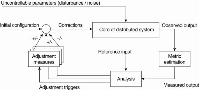
The core of a feedback
control system is formed by the components that need to be managed. These
components are assumed to be driven through controllable input parameters, but
their behavior may be influenced by all kinds of uncontrollable input, also
known as disturbance or noise input. Although disturbance will often come from
the environment in which a distributed system is executing, it may well be the
case that unanticipated component interaction causes unexpected behavior.
There are essentially three
elements that form the feedback control loop. First, the system itself needs to
be monitored, which requires that various aspects of the system need to be
measured. In many cases, measuring behavior is easier said than done. For
example, round-trip delays in the Internet may vary wildly, and also depend on
what exactly is being measured. In such cases, accurately estimating a delay
may be difficult indeed. Matters are further complicated when a node A needs to
estimate the latency between two other completely different nodes B and C,
without being able to intrude on either two nodes. For reasons as this, a
feedback control loop generally contains a logical metric estimation component.
[Page 61]
Another part of the feedback
control loop analyzes the measurements and compares these to reference values.
This feedback analysis component forms the heart of the control loop, as it
will contain the algorithms that decide on possible adaptations.
The last group of components
consist of various mechanisms to directly influence the behavior of the system.
There can be many different mechanisms: placing replicas, changing scheduling
priorities, switching services, moving data for reasons of availability,
redirecting requests to different servers, etc. The analysis component will
need to be aware of these mechanisms and their (expected) effect on system
behavior. Therefore, it will trigger one or several mechanisms, to subsequently
later observe the effect.
An interesting observation
is that the feedback control loop also fits the manual management of systems.
The main difference is that the analysis component is replaced by human
administrators. However, in order to properly manage any distributed system,
these administrators will need decent monitoring equipment as well as decent
mechanisms to control the behavior of the system. It should be clear that
properly analyzing measured data and triggering the correct actions makes the
development of self-managing systems so difficult.
It should be stressed that
Fig. 2-16 shows the logical organization of a self-managing system, and as such
corresponds to what we have seen when discussing software architectures.
However, the physical organization may be very different. For example, the
analysis component may be fully distributed across the system. Likewise, taking
performance measurements are usually done at each machine that is part of the
distributed system. Let us now take a look at a few concrete examples on how to
monitor, analyze, and correct distributed systems in an automatic fashion.
These examples will also illustrate this distinction between logical and
physical organization.
2.4.2. Example: Systems
Monitoring with Astrolabe
As our first example, we
consider Astrolabe (Van Renesse et al., 2003), which is a system that can
support general monitoring of very large distributed systems. In the context of
self-managing systems, Astrolabe is to be positioned as a general tool for
observing systems behavior. Its output can be used to feed into an analysis
component for deciding on corrective actions.
Astrolabe organizes a large
collection of hosts into a hierarchy of zones. The lowest-level zones consist
of just a single host, which are subsequently grouped into zones of increasing
size. The top-level zone covers all hosts. Every host runs an Astrolabe
process, called an agent, that collects information on the zones in which that
host is contained. The agent also communicates with other agents with the aim
to spread zone information across the entire system.
Each host maintains a set of
attributes for collecting local information. For example, a host may keep track
of specific files it stores, its resource usage, and so on. Only the attributes
as maintained directly by hosts, that is, at the lowest level of the hierarchy
are writable. Each zone can also have a collection of attributes, but the
values of these attributes are computed from the values of lower level zones.
[Page 62]
Consider the following
simple example shown in Fig. 2-17 with three hosts, A, B, and C grouped into a
zone. Each machine keeps track of its IP address, CPU load, available free
memory, and the number of active processes. Each of these attributes can be
directly written using local information from each host. At the zone level,
only aggregated information can be collected, such as the average CPU load, or
the average number of active processes.
Figure 2-17. Data collection
and information aggregation in Astrolabe.
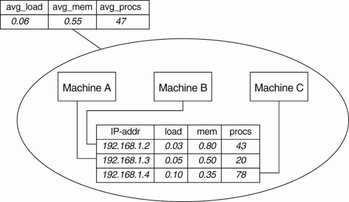
Fig. 2-17 shows how the
information as gathered by each machine can be viewed as a record in a
database, and that these records jointly form a relation (table). This
representation is done on purpose: it is the way that Astrolabe views all the
collected data. However, per zone information can only be computed from the
basic records as maintained by hosts.
Aggregated information is
obtained by programmable aggregation functions, which are very similar to
functions available in the relational database language SQL. For example,
assuming that the host information from Fig. 2-17 is maintained in a local
table called hostinfo, we could collect the average number of processes for the
zone containing machines A, B, and C, through the simple SQL query
SELECT AVG(procs) AS
avg_procs FROM hostinfo
Combined with a few
enhancements to SQL, it is not hard to imagine that more informative queries
can be formulated.
Queries such as these are
continuously evaluated by each agent running on each host. Obviously, this is
possible only if zone information is propagated to all nodes that comprise
Astrolabe. To this end, an agent running on a host is responsible for computing
parts of the tables of its associated zones. Records for which it holds no
computational responsibility are occasionally sent to it through a simple, yet
effective exchange procedure known as gossiping. Gossiping protocols will be
discussed in detail in Chap. 4. Likewise, an agent will pass computed results
to other agents as well.
[Page 63]
The result of this
information exchange is that eventually, all agents that needed to assist in
obtaining some aggregated information will see the same result (provided that
no changes occur in the meantime).
2.4.3. Example: Differentiating Replication Strategies in Globule
Let us now take a look at Globule,
a collaborative content distribution network (Pierre and van Steen, 2006).
Globule relies on end-user servers being placed in the Internet, and that these
servers collaborate to optimize performance through replication of Web pages.
To this end, each origin server (i.e., the server responsible for handling
updates of a specific Web site), keeps track of access patterns on a per-page
basis. Access patterns are expressed as read and write operations for a page,
each operation being timestamped and logged by the origin server for that page.
In its simplest form,
Globule assumes that the Internet can be viewed as an edge-server system as we
explained before. In particular, it assumes that requests can always be passed
through an appropriate edge server, as shown in Fig. 2-18. This simple model
allows an origin server to see what would have happened if it had placed a
replica on a specific edge server. On the one hand, placing a replica closer to
clients would improve client-perceived latency, but this will induce traffic
between the origin server and that edge server in order to keep a replica
consistent with the original page.
Figure 2-18. The edge-server
model assumed by Globule.
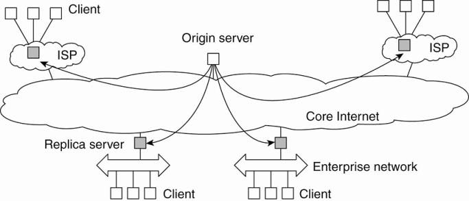
When an origin server
receives a request for a page, it records the IP address from where the request
originated, and looks up the ISP or enterprise network associated with that
request using the WHOIS Internet service (Deutsch et al., 1995). The origin
server then looks for the nearest existing replica server that could act as
edge server for that client, and subsequently computes the latency to that
server along with the maximal bandwidth. In its simplest configuration, Globule
assumes that the latency between the replica server and the requesting user
machine is negligible, and likewise that bandwidth between the two is
plentiful.
[Page 64]
Once enough requests for a
page have been collected, the origin server performs a simple "what-if
analysis." Such an analysis boils down to evaluating several replication
policies, where a policy describes where a specific page is replicated to, and
how that page is kept consistent. Each replication policy incurs a cost that
can be expressed as a simple linear function:
cost=(w1xm1)+(w2xm2)+ . . .+(wnxmn)
where mk denotes a
performance metric and wk is the weight indicating how important that metric
is. Typical performance metrics are the aggregated delays between a client and
a replica server when returning copies of Web pages, the total consumed bandwidth
between the origin server and a replica server for keeping a replica
consistent, and the number of stale copies that are (allowed to be) returned to
a client (Pierre et al., 2002).
For example, assume that the
typical delay between the time a client C issues a request and when that page
is returned from the best replica server is dC ms. Note that what the best
replica server is, is determined by a replication policy. Let m1 denote the
aggregated delay over a given time period, that is, m1=Σ dC. If the origin
server wants to optimize client-perceived latency, it will choose a relatively
high value for w1. As a consequence, only those policies that actually minimize
m1 will show to have relatively low costs.
In Globule, an origin server
regularly evaluates a few tens of replication polices using a trace-driven
simulation, for each Web page separately. From these simulations, a best policy
is selected and subsequently enforced. This may imply that new replicas are installed
at different edge servers, or that a different way of keeping replicas
consistent is chosen. The collecting of traces, the evaluation of replication
policies, and the enforcement of a selected policy is all done automatically.
There are a number of subtle
issues that need to be dealt with. For one thing, it is unclear how many
requests need to be collected before an evaluation of the current policy can
take place. To explain, suppose that at time Ti the origin server selects
policy p for the next period until Ti+1. This selection takes place based on a
series of past requests that were issued between Ti-1 and Ti. Of course, in
hindsight at time Ti+1, the server may come to the conclusion that it should
have selected policy p* given the actual requests that were issued between Ti
and Ti+1. If p* is different from p, then the selection of p at Ti was wrong.
As it turns out, the
percentage of wrong predictions is dependent on the length of the series of
requests (called the trace length) that are used to predict and select a next
policy. This dependency is sketched in Fig. 2-19. What is seen is that the
error in predicting the best policy goes up if the trace is not long enough.
This is easily explained by the fact that we need enough requests to do a proper
evaluation. However, the error also increases if we use too many requests. The
reason for this is that a very long trace length captures so many changes in
access patterns that predicting the best policy to follow becomes difficult, if
not impossible. This phenomenon is well known and is analogous to trying to
predict the weather for tomorrow by looking at what happened during the
immediately preceding 100 years. A much better prediction can be made by just
looking only at the recent past.
[Page 65]
Figure 2-19. The dependency
between prediction accuracy and trace length.
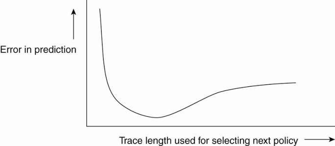
Finding the optimal trace
length can be done automatically as well. We leave it as an exercise to sketch
a solution to this problem.
2.4.4. Example: Automatic Component Repair Management in Jade
When maintaining clusters of
computers, each running sophisticated servers, it becomes important to
alleviate management problems. One approach that can be applied to servers that
are built using a component-based approach, is to detect component failures and
have them automatically replaced. The Jade system follows this approach
(Bouchenak et al., 2005). We describe it briefly in this section.
Jade is built on the Fractal
component model, a Java implementation of a framework that allows components to
be added and removed at runtime (Bruneton et al., 2004). A component in Fractal
can have two types of interfaces. A server interface is used to call methods
that are implemented by that component. A client interface is used by a component
to call other components. Components are connected to each other by binding
interfaces. For example, a client interface of component C1 can be bound to the
server interface of component C2. A primitive binding means that a call to a
client interface directly leads to calling the bounded server interface. In the
case of composite binding, the call may proceed through one or more other
components, for example, because the client and server interface did not match
and some kind of conversion is needed. Another reason may be that the connected
components lie on different machines.
[Page 66]
Jade uses the notion of a
repair management domain. Such a domain consists of a number of nodes, where
each node represents a server along with the components that are executed by
that server. There is a separate node manager which is responsible for adding
and removing nodes from the domain. The node manager may be replicated for
assuring high availability.
Each node is equipped with
failure detectors, which monitor the health of a node or one of its components
and report any failures to the node manager. Typically, these detectors
consider exceptional changes in the state of component, the usage of resources,
and the actual failure of a component. Note that the latter may actually mean
that a machine has crashed.
When a failure has been
detected, a repair procedure is started. Such a procedure is driven by a repair
policy, partly executed by the node manager. Policies are stated explicitly and
are carried out depending on the detected failure. For example, suppose a node
failure has been detected. In that case, the repair policy may prescribe that
the following steps are to be carried out:
1. Terminate every binding between a
component on a nonfaulty node, and a component on the node that just failed.
2. Request the node manager to start and
add a new node to the domain.
3. Configure the new node with exactly the
same components as those on the crashed node.
4. Re-establish all the bindings that were
previously terminated.
In this example, the repair
policy is simple and will only work when no crucial data has been lost (the
crashed components are said to be stateless).
The approach followed by
Jade is an example of self-management: upon the detection of a failure, a
repair policy is automatically executed to bring the system as a whole into a
state in which it was before the crash. Being a component-based system, this
automatic repair requires specific support to allow components to be added and
removed at runtime. In general, turning legacy applications into self-managing
systems is not possible.