|
DCS861D: The User Interface from Front to Back |
|
Augmented Reality |
Definition
Augmented Reality (AR):
- Variation of Virtual Reality in which the user sees the real world, with virtual objects superimposed upon or composited within the real world.
- AR supplements reality, rather than completely replacing it.
- Ideally, it should appear to the user that the virtual and real objects coexisted in the same space
- AR possesses three desired characteristics:
1)
Combines real and virtual
2) Interactive in real time
3) Registered in 3D
Real desk with virtual lamp and two virtual chairs
- Augmented Reality enhances a user's perception of and interaction with the real world
- Virtual objects display information that the user cannot directly detect with his own senses.
- Since many operations require manipulation or modification of a real environment, the virtual objects provide information that helps a user perform a realworld task.
- AR is a specific example of what Fred Brooks calls Intelligence Amplification (IA): using the computer as a tool that makes a task easier for a human to perform.
AUGMENTED
REALITY VERSUS VIRTUAL REALITY
Similarities between VR and AR
environments
- Both environments use computer generated three-dimensional scene which requires high performance computer graphics to provide inadequate level of realism.
- Both worlds are interactive.
- Their users require real-time response from the system to be able to interact with it in an effective manner.
- The uses are immersed in their environment.
Differences between VR and AR environments are in their treatment of the real world
- In AR virtual images are merged with the real view to create the augmented display.
- In VR the whole environment is virtual.
- Augmented Reality augments the user's view of the real world by composing 3D virtual objects with their real world counterparts, necessitating that the user maintains a sense of presence in that world.
- Virtual Reality immerse a user inside a virtual world that completely replaces the real world outside.
Milgram describes how Augmented Reality and Virtual Reality are related.
Milgram's Reality-Virtuality
Diagram
P.Milgram and F.Kishino,A Taxonomy of Mixed Reality Visual Displays, IEICE
Trans.Information Systems,vol.
E77-D,no.12,1994,pp.1321-1329.
- Real world and a totally virtual environment are at the two ends of this continuum with the middle region called Mixed Reality.
- Augmented reality lies near the real world end of the line with the predominate perception being the real world augmented by computer generated data.
- Augmented virtuality is a term created by Milgram to identify systems which are mostly synthetic with some real world imagery added such as texture mapping video onto virtual objects.
Potential AR Applications
- Medical Visualization
- Visualization and training aid for surgery.
- Collect 3D datasets of a patient in real time, using noninvasive sensors like Magnetic Resonance Imaging (MRI), Computed Tomography scans (CT), or ultrasound imaging.
- Datasets then be rendered and combined in real time with a view of the real patient.
- AR provides an internal view without the need for larger incisions.
- Information from the noninvasive sensors directly displayed on the patient, showing exactly where to perform the operation.
- Several projects:
- UNC Chapel Hill
- Trial runs of scanning the womb of a pregnant woman with an ultrasound sensor
- Generating a 3D representation of the fetus inside the womb
- Displaying that in a seethrough HMD
- Goal : endow the doctor with the ability to see the moving fetus inside the womb
 Virtual fetus inside womb of
pregnant woman (UNC)
Virtual fetus inside womb of
pregnant woman (UNC)
Laparoscopy suffers from a number of visual
limitations:
1. Limited field of view for the surgeon
2. Lack of good
hand-eye coordination
3. Two-dimensional imagery
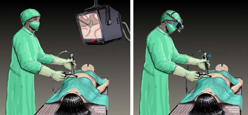
Left: Traditional View with 2D Monitor
Right: View with HMD
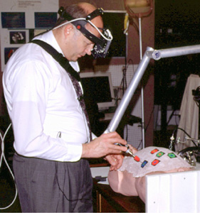
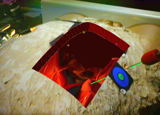
Left: Piercing a small foam target inside the abdominal cavity of the model
Right: What the surgeon sees
MIT Medical Vision Group: MRI or CT data directly registered onto the patient
- Enhanced Reality Visualization
- Peel back the MRI skin and see where the internal structures are located relative to the viewpoint of the camera
Superposition of MRI Scans on patients
- Laser Scanning creates registration points
- Coordinates of points on the patient's skin obtained with a laser scanner to collect 3D data of the patient's scalp surface as positioned on the operating table.
- The scanner consists of a laser mounted on a stepper motor at one end of a bar and a camera on the other end.
- The laser beam is split and projects a plane of light at the angle determined by the stepper motor.
- Each pixel of the camera defines a ray going through the center of projection of the camera.
- When the plane of light hits an object, a visible line appears on the object.
- Intersecting the laser plane with the optical ray yields a 3D point that lies on the object.
The positional data of the patient is acquired with high positional accuracy
(< 1 mm) while avoiding direct contact with the patient.
The points of interest on the patient's head are selected using a simple mouse
interface and are shown in red.
- Manufacturering and Repair
- KARMA (Knowledge-based Augmented Reality for Maintenance Assistance)
Prototype system that uses a see-through
head-mounted display to explain simple end-user maintenance for a laser printer
Left Figure: Attached several Logitech 3D trackers (the small triangles in
the figure shown
above) to key components of the printer, allowing the system to monitor
their position and orientation
Right Figure: shows a virtual world designed by
KARMA, viewed ``live'' through a see-through head-mounted display.
- Boeing (
- AR technology to guide a technician in building a wiring harness that forms part of an airplane's electrical system.
- Currently, technicians use large physical layout boards to construct such harnesses, and Boeing requires several warehouses to store all these boards.
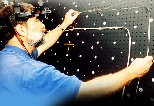
- System guides a mechanic who, although skilled, may not have experience with a given piece of equipment.
- By using AR, the mechanic is guded step-by-step through a disassembly procedure, thus reducing errors and risks while increasing productivity and knowledge to the mechanic.
- This optical see-through AR system uses simple line drawings and text overlayed onto
the physical world.
- The system consists of a Polhemus fastrack electromagnetic tracker and Virtual Vision VCAP - 10000 HMD. The application was written in C++ as a standard Windows 32 application and has been ported to Linux.
- Features of Augmented Reality System:
1. Direct placement of information
2. Can be tuned to intended job training
3. Technology can be applicable to any sequenced procedure
4. Applications include assembly, disassembly, maintenance and training
5. Utilizes either optical see-through or video see-through
6. Can reduce or potentially eliminate paper training materia
- Annotation and Visualization
Used to annotate objects and
environments with public or private information.
- European ComputerIndustry Research Centre (ECRC), a user can point at parts of an engine model and the AR system displays the name of the part that is being pointed to.
The user points at the exhaust
manifold on an engine model, and the label "exhaust manifold"
appears.
Windows on
the World - 2D Windows for 3D Augmented Reality
Windows attached from a standard user interface
onto specific locations in the world
- Figure shows a virtual world populated by three X windows, photographed ``live'' through a see-through head-mounted display.
- Window at the right is an xload load-average meter that is fixed to the corner of a portable workstation.
- The xpostit window at the upper left is attached to the 3D tracker ``bolo tie'' so it moves when the user moves.
- The window at the bottom is the control panel for a hypermedia system. It is fixed to the head-mounted display, so it always occupies the same location relative to the user's head.
Augmented
Reality through Graphic Overlays on Stereovideo (
- Used to supplement visualization during difficult viewing conditions.
e.g. wireframe lines drawn on
top of a space shuttle bay interior, while in orbit.
- The lines make it easier to see the geometry of the shuttle bay.
- Similarly, virtual lines and objects could aid navigation and scene understanding during poor visibility conditions, such as underwater or in fog.
Augmented
Reality for Construction
- Entertainment
- "Virtual Sets"
- Merge real actors with virtual backgrounds, in real time and in 3D.
- Actors stand in front of a large blue screen, with a computercontrolled motion camera videotaping the scene.
- Since the camera's location is tracked, and the actor's motions are scripted, it is possible to digitally composite the actor into a 3D virtual background.
e.g. an actor might appear to stand inside a large virtual spinning ring, where the front part of the ring covers the actor while the rear part of the ring is covered by the actor.
- Military aircraft navigation and targeting
- HeadUp Displays (HUDs) and HelmetMounted Sights (HMS)
- Superimpose vector graphics upon the pilot's view of the real world.
- Besides providing basic navigation and flight information, these graphics are sometimes registered with targets in the environment, providing a way to aim the aircraft's weapons.
e.g., the chin turret in a helicopter gunship can be slaved to the pilot's HMS, so the pilot can aim the chin turret simply by looking at the target.
AR System Characteristics
Augmentation
- Applies to all senses
- Most research focused on blending real and virtual images and graphics
- Some work on haptics and sound
Optical vs. Video Augmentation
- How to accomplish the combining of real and virtual:
- Choices available: optical and video technologies.
- Seethrough HMD lets the user see the real world, with virtual objects superimposed by optical or video technologies.
 Sim Eye XL100A ( Kaiser Electro-Optics, Inc)
- Work by placing optical combiners in front of the user's eyes.
- Combiners are partially transmissive, to see the real world
- Combiners are partially reflective, to see virtual images bounced off the combiners from headmounted monitors.
- Similar in nature to HeadUp Displays (HUDs) commonly used in military aircraft
- Virtual Retinal Display - low power lasers draw on retina
- Video seethrough HMDs work by combining a closedview HMD with one or two headmounted video cameras
(UNC,
- Video cameras provide user's view of the real world.
- Video from these cameras is combined with the graphic images created by the scene generator, blending the real and virtual.
- Result is sent to the monitors in front of the user's eyes in the closedview HMD.
- Video compositing
- Simple way - chromakeying: a technique used in many video special effects.
- Background of the computer graphic images set to a specific color (typically blue or green)
- No virtual object uses this color.
- Combining step replaces all green areas with the corresponding parts from the video of the real world.
- More sophisticated - compositing using depth information.
- Depth information at each pixel for the real world images, alllow combining real and virtual images by a pixelbypixel depth comparison.
- Allows real objects to cover virtual objects and viceversa.
- Alternative to HMDs - monitorbased configurations
- Version 1:
- One or two video cameras view the environment.
- Video of the real world and the graphic images generated by a scene generator are combined, just as in the video seethrough HMD case and displayed in a monitor in front of the user.
- User does not wear the display device.
- Optionally, images may be displayed in stereo on the monitor,requiring the use of tereo glasses.
- Version 2:
- Monitors and combiners are fixed in space
- User moves head to look through the combiners
- Relative advantages and disadvantages of optical and video approaches
- Optical approach advantages over video:
1) Simplicity:
- Optical blending is simpler and cheaper than video blending.
- Optical approaches have only one "stream" of video: the graphic images.
- Real world is seen directly through the combiners, and that time delay is generally a few nanoseconds.
- Optical seethrough HMDs with narrow fieldofview combiners offer views of the real world that have little distortion.
- Video blending must deal with separate video streams for the real and virtual images.
- Both streams have inherent delays in the tens of milliseconds.
- Digitizing video images usually adds at least one frame time of delay to the video stream, where a frame time is how long it takes to completely update an image.
- A monitor that completely refreshes the screen at 60 Hz has a frame time of 16.67 ms.
- The two streams of real and virtual images must be properly synchronized, or temporal distortion results.
- Video cameras have some amount of distortion that must be compensated for, along with any distortion from the optics in front of the display devices.
- Since video requires cameras and combiners, video will probably be more expensive and complicated to build than opticalbased systems.
2) Resolution:
- Video blending limits the resolution of what the user sees, both real and virtual, to the resolution of the display devices.
- Current display resolutiuons are far less than the resolving power of the fovea.
- Optical seethrough also shows the graphic images at the resolution of the display device, but the user's view of the real world is not degraded.
3) Safety:
- Video seethrough HMDs are modified closedview HMDs.
- With the power is cut off, the user becomes blind.
- For seethrough HMD, the user has a direct view of the real world when power is off.
4) No eye offset:
- With video seethrough, user's view of the real world is provided by the video cameras.
- Places "eyes" where the video cameras are.
- Difference between camera and eye locations introduces displacements.
- Avoid the eye offset problem through the use of mirrors to create another set of optical paths that mimic the paths directly into the user's eyes.
- Video blending offers the following advantages over optical blending:
1) Flexibility in composition strategies:
- Disadvantage of optical seethrough - virtual objects do not completely obscure real world objects, because optical combiners allow light from both virtual and real sources.
- Virtual objects appear ghostlike and semitransparent.
- Damages illusion of reality because occlusion is one of the strongest depth cues.
- Advantage of video seethrough - more flexible about merging real and virtual images.
- Both the real and virtual are available in digital form
- Video seethrough compositors can, on a pixelbypixel basis, take the real, or the virtual, or some blend between the two to simulate transparency.
2) Wide fieldofview:
- Degree of distortion in a optical system is a function of the radial distance away from the optical axis.
- A digitized image taken through a distorted optical system can be undistorted by applying image processing techniques to unwarp the image.
- Distortions of the user's view of the real world must be corrected optically
- Complex optics are expensive and add weight to the HMD.
3) Real and virtual view delays can be matched:
- Optical seethrough HMDs offer instantaneous view of the real world, but a delayed view of the virtual.
- This temporal mismatch can cause problems.
- Video approachesallow delay of video of real world to match the delay from the virtual image stream.
4) Additional registration strategies:
- Optical seethrough -
- Only information the system has about the user's head location comes from the head tracker.
- Video blending provides another source of information: the digitized image of the real scene.
- Digitized image means that video approaches can employ additional registration strategies unavailable to optical approaches.
Focus and Contrast
Focus
- Videobased system:
- Combined virtual and real image projected at the same distance by monitor or HMD optics.
- Video camera's depthoffield and focus settings selectively focus parts of the real world
- Typical graphics software rendered with a pinhole model - all graphic objects, regardless of distance, are in focus.
- Solution:
- Graphics rendered to simulate a limited depthoffield
- Use video camera with an autofocus lens
- Optical-based system:
- Virtual image is projected at some fixed distance away from the user.
- While real objects are at varying distances from the user, the virtual objects are all projected to the same distance.
- If virtual and real distances are not matched for the particular objects that the user is viewing, it may not be possible to clearly see both simultaneously.
Contrast
- Large dynamic range of illumination in real environments and in what the human eye can detect
- Brightness of real and virtual objects should be matched
- Worst case scenario - system must match a very large range of brightness levels
- Eye is a logarithmic detector, where the brightest light that it can handle is about eleven orders of magnitude greater than the smallest, including both darkadapted and lightadapted eyes.
- In any one adaptation state, the eye can cover about six orders of magnitude.
- Most display devices cannot come close to this level of contrast.
- Optical technologies problems:
- User has a direct view of the real world
- If real environment is too bright, it will wash out the virtual image.
- If the real environment is too dark, the virtual image will wash out the real world.
- Video technologies problems:
- Contrast problems are not as severe with video
- Video cameras have limited dynamic response
- View of both real and virtual is generated by the monitor
- So everything must be clipped or compressed into the monitor's dynamic range.
Portability
- Almost all Virtual Environment systems
- User not encouraged to walk around
- User navigates by "flying" through the environment, walking on a treadmill, or driving some mockup of a vehicle.
- Some AR applications
- Support a user's walk around a large environment.
- AR requires that the user actually be at the place where the task is to take place
e.g. a mechanic
needs move about a jet engine, and must physically move the display
- AR system place a premium on portability, especially the ability to walk outside controlled environments.
- The scene generator, HMD, and tracking system must all be selfcontained and capable of surviving exposure to the environment.
Comparison with Virtual Environments
1) Scene generator:
- Rendering:
- VE systems require realistic images because they completely replace the real world with the virtual environment.
- Not a major problems in AR
- Virtual images only supplement the real world
- Fewer virtual objects required, not necessarily realistically rendered, in order to serve the purposes of the application.
- e.g., in the annotation applications, text and 3D wireframe drawings may suffice.
2) Display device:
- VE systems:
- use full color
- high resolution display
- AR systems
- AR does not replace the real world.
- e.g., monochrome displays may be adequate for some AR applications
- Optical seethrough HMDs with a small fieldofview may be satisfactory because the user can still see the real world with his peripheral vision;
- Seethrough HMD does not shut off the user's normal fieldofview.
- Resolution of the monitor in an optical seethrough HMD might be lower than what a user would tolerate in a VE application, since the optical seethrough HMD does not reduce the resolution of the real environment.
3) Tracking and sensing:
- Tracking requirements for AR are much stricter than those for VE systems.
- Reason: registration problem
Registration
The Registration Problem
- Objects in real and virtual worlds must be properly aligned
- What angular accuracy is needed for good registration in Augmented Reality?
- Demonstration:
- Take out a dime and hold it at arm's length, so that it looks like a circle.
- The diameter of the dime covers about 1.2 to 2.0 degrees of arc, depending on arm length. (In comparison, the width of a full moon is about 0.5 degrees of arc!)
- Imagine a virtual object superimposed on a real object, but offset by the diameter of the full moon. Such a difference would be easy to detect.
- Angular accuracy required is a small fraction of a degree.
- Lower limit is bounded by the resolving power of the human eye
- Central part of the retina - the fovea - has the highest density of color-detecting cones, about 120 per degree of arc, corresponding to a spacing of half a minute of arc.
- Observers can differentiate between a dark and light bar grating when each bar subtends about one minute of arc
- Existing HMD trackers and displays are not capable of providing one minute of arc in accuracy
- Present achievable accuracy is much worse than that ultimate lower bound
- In practice, errors of a few pixels are detectable in modern HMDs.
- Registration errors are difficult to adequately control because of the high accuracy requirements and the numerous sources of error.
- These sources of error can be divided into two types:
- Static - cause registration errors even when the user's viewpoint and the objects in the environment remain completely still
- Dynamic - have no effect until either the viewpoint or the objects begin moving.
- For current HMD-based systems, dynamic errors are by far the largest contributors to registration errors, but static errors cannot be ignored
Static Errors
- Sources of static errors:
- Optical distortion
- Errors in the tracking system
- Mechanical misalignments
- Incorrect viewing parameters (e.g., field of view, tracker-to-eye position and orientation, interpupillary distance)
1) Optical Distortion:
- Exists in most camera and lens systems
- Optical distortions are systematic errors, so they can be mapped and compensated.
2) Errors in the tracking system:
- Tracking and sensing system errors are the most serious type of static registration errors.
- Not easy to measure and eliminate, because that requires another "3-D ruler" that is more accurate than the tracker being tested.
- Errors are non-systematic and difficult to fully characterize.
- Almost all commercially-available tracking systems are not accurate enough to satisfy the requirements of AR systems.
3) Mechanical misalignments:
- Discrepancies between the model or specification of the hardware and the actual physical properties of the real system.
e.g., combiners, optics, and monitors in an optical see-through HMD may not be at the expected relative distances or orientations.
- If the frame is not sufficiently rigid, the various component parts may change their relative positions as the user moves around, causing errors.
- Mechanical misalignments can cause subtle changes in the position and orientation of the projected virtual images that are difficult to compensate.
- Some alignment errors can be calibrated, for many others it may be more effective to "build it right" initially.
4) Incorrect viewing parameters:
- Special case of alignment errors where calibration techniques can be applied.
- Viewing parameters specify how to convert the reported head or camera locations into viewing matrices used by the scene generator to draw the graphic images.
- For an HMD-based system, these parameters include:
- Center of projection and viewport dimensions
- Offset, both in translation and orientation, between the location of the head tracker and the user's eyes
- Field of view
- Incorrect viewing parameters cause systematic static errors.
e.g., head tracker located above a user's eyes.
- If the vertical translation offsets between the tracker and the eyes are too small, all the virtual objects will appear lower than they should.
- Viewing parameter estimation
- Manual adjustments - non-systematic
- Direct measurement of parameters using various measuring tools and sensors.
- View-based tasks
Ask user to perform various tasks that set up geometric constraints.
- Video-based systems
- Extensive body of literature in robotics and photogrammetryon camera calibration techniques
- Techniques compute a camera's viewing parameters by taking several pictures of an object of fixed and sometimes unknown geometry.
Dynamic Errors
- Occur because of system delays, or lags.
- End-to-end system delay defined as the time difference between the moment that the tracking system measures the position and orientation of the viewpoint to the moment when the generated images corresponding to that position and orientation appear in the displays.
- These delays exist because each component in an Augmented Reality system requires some time to do its job.
- Delays in
- tracking subsystem time
- communication time
- image generation time (to frame buffer)
- scanout time (from the frame buffer to displays)
- End-to-end delays of 100 ms are fairly typical on existing systems.
- End-to-end system delays cause registration errors only when motion occurs.
- System delays degrade the illusion that the real and virtual worlds coexist
- Typical end-to-end lag of 100 ms and a moderate head rotation rate of 50 degrees per second, the angular dynamic error is 5 degrees.
- At a 68 cm arm length, this results in registration errors of almost 60 mm.
- System delay is the largest single source of registration error in existing AR systems, outweighing all others combined
- Methods used to reduce dynamic registration:
1. Reduce system lag
2. Reduce apparent lag
3. Match temporal streams (with video-based systems)
4. Predict future locations
1) Reduce system lag:
- Most direct approach - reduce or eliminate system delays.
- No delays, No dynamic errors.
- Modern scene generators are usually built for throughput, not minimal latency
- System delays are not likely to completely disappear anytime soon.
- e.g.,
- Registration errors must be kept to a small fraction of a degree.
- At moderate head rotation rate of 50 degrees per second, system lag must be 10 ms or less to keep angular errors below 0.5 degrees.
- Just scanning out a frame buffer to a display at 60 Hz requires 16.67 ms.
2) Reduce apparent lag:
- Method 1: Image deflection
- Scene generator renders an image much larger than needed to fill the display.
- Just before scanout, the system reads the most recent orientation report.
- Orientation value is used to select the fraction of the frame buffer to send to the display, since small orientation changes are equivalent to shifting the frame buffer output horizontally and vertically.
- Method 2: Image warping
- Image deflection does not work on translation
- After the scene generator renders the image based upon the head tracker reading, small adjustments in orientation and translation could be done after rendering by warping the image.
- These techniques assume knowledge of the depth at every pixel, and the warp must be done much more quickly than rerendering the entire image.
3) Match temporal streams:
- Video-based AR systems
- Video camera and digitization hardware impose inherent delays on the user's view of the real world.
- Allows temporal streams of the real and virtual images to be matched.
- Additional delay is added to the video from the real world to match the scene generator delays in generating the virtual images.
- Now both real and virtual objects are delayed in time.
- It is a major problem in the related area of telepresence systems and will not be easy to overcome.
4) Predict:
- Predict the future viewpoint and object locations
- If future locations are known, the scene can be rendered with these future locations, rather than the measured locations.
- When scene finally appears, viewpoints and objects have moved to the predicted locations, and the graphic images are correct at the time they are viewed.
- For short system delays (under ~80 ms), prediction has been shown to reduce dynamic errors by up to an order of magnitude.
- Accurate predictions require a system built for real-time measurements and computation.
Vision-based Techniques
- Image processing or computer vision techniques usedto aid registration
- Some AR applications place fiducials in the environment, e.g. LEDs or special markers.
- Recent ultrasound experiments at UNC Chapel Hill have used colored dots as fiducials.
- Locations or patterns of the fiducials are assumed to be known.
- Image processing detects the locations of the fiducials
- Used to make corrections that enforce proper registration.
- Routines assume that one or more fiducials are visible at all times
- Results can be accurate to one pixel, close as one can get with video techniques.
Figure: Virtual arrow and a virtual chimney exactly aligned with their
desired points on two real objects.
- Real objects each have an LED to aid the registration.
- Figures show dots with a circular pattern as the fiducials. The registration is also nearly perfect.
Left Figure: Real skull with five fiducials.
Right Figure: Virtual wireframe skull registered
with real skull.
- Template matching to achieve registration.
- Template images of the real object are taken from a variety of viewpoints.
- Used to search the digitized image for the real object.
- Once that is found, a virtual wireframe can be superimposed on the real object.
- Recent approaches in video-based matching avoid the need for any calibration
- Represents virtual objects in a non-Euclidean, affine frame of reference that allows rendering without knowledge of camera parameters.
- Extracts contours from the video of the real world, then uses an optimization technique to match the contours of the rendered 3-D virtual object with the contour extracted from the video.
- Calibration-free approaches may not recover all the information required to perform all potential AR tasks.
- e.g., approaches do not recover true depth information, useful when compositing the real and the virtual.
- Fiducials techniques determine the relative projective relationship between the objects in the environment and the video camera.
- Does not provide absolute locations of the objects and the camera.
- Absolute locations are needed to include virtual and real objects that are not tracked by the video camera, such as a 3-D pointer or other virtual objects not directly tied to real objects in the scene.
- Additional sensors can aid registration.
- e.g., laser rangefinder used to acquire an initial depth map of the real object in the environment.
- Given a matching virtual model, the system can match the depth maps from the real and virtual until they are properly aligned, and provides the information needed for registration.
Sensing
AR demands more from trackers and sensors than VR in three areas:
- Greater input variety and bandwidth
- Higher accuracy
- Longer range
Input variety and bandwidth
- VE systems:
- Primarily built to handle output bandwidth: images displayed, sounds generated, etc.
- Input bandwidth is tiny: the locations of the user's head and hands, the outputs from the buttons and other control devices, etc.
- AR systems:
- Need a greater variety of input sensors and much more input bandwidth.
- Greater variety of possible input sensors than output displays.
- Outputs are limited to the five human senses. I
- Inputs come from anything a sensor can detect.
- Conceptually, anything not detectable by human senses but detectable by machines might be transduced into something that a user can sense in an AR system.
High accuracy
- Accuracy requirements for the trackers and sensors are driven by the accuracies needed for visual registration.
- Registration is only as accurate as the tracker.
- AR system needs trackers that are accurate to around a millimeter and a tiny fraction of a degree, across the entire working range of the tracker.
- Few trackers meet this specification.
- Every technology has weaknesses:
- Some mechanical trackers are accurate enough, although they tether the user to a limited working volume.
- Magnetic trackers are vulnerable to distortion by metal in the environment, which exists in many desired AR application environments.
- Ultrasonic trackers suffer from noise and are difficult to make accurate at long ranges because of variations in the ambient temperature.
- Optical technologies have distortion and calibration problems.
- Inertial trackers drift with time.
- Optical technologies show the most promise due to trends toward high-resolution digital cameras, real-time photogrammetric techniques, and structured light sources that result in more signal strength at long distances.
- Future tracking systems that can meet the stringent requirements of AR will probably be hybrid systems such as a combination of inertial and optical technologies.
- Using multiple technologies opens the possibility of covering for each technology's weaknesses by combining their strengths.
Longer range
- Few trackers are built for accuracy at long ranges
- e.g.
- Motion capture applications track an actor's body parts to control a computer-animated character or for the analysis of an actor's movements.
- Fine for position recovery, but not for orientation.
- Orientation recovery based upon the computed positions.
- Small errors in those positions can cause orientation errors of a few degrees, which is too large for AR systems.
- Scalable tracking systems for HMDs:
- Scalable system is one that can be expanded to cover any desired range by adding more modular components to the system.
- Accomplished by building a cellular tracking system, where only nearby sources and sensors are used to track a user.
- As the user walks around, the set of sources and sensors changes, thus achieving large working volumes while avoiding long distances between the current working set of sources and sensors.
- While scalable trackers can be effective, they are complex and by their very nature have many components, making them relatively expensive to construct.
- Global Positioning System (GPS)
- Used to track the locations of vehicles almost anywhere on the planet.
- May be useful as one part of a long range tracker for AR systems.
- Best reported accuracy is approximately one centimeter, assuming that many measurements are integrated (so that accuracy is not generated in real time)
Other Systems
- Office of the Future
- Use real-time computer vision techniques to dynamically extract per-pixel depth and reflectance information for the visible surfaces in the office including walls, furniture, objects, and people, and then to either project images on the surfaces, render images of the surfaces, or interpret changes in the surfaces.
- Designate every-day (potentially irregular) real surfaces in the office to be used as spatially immersive display surfaces
- Project high-resolution graphics and text onto those surfaces.
- Transmit dynamic image-based models over a network for display at a remote site.
- Interpret dynamic changes in the surfaces for the purposes of tracking, interaction, or augmented reality applications.
To accomplish the simultaneous capture and
display:
- Ceiling lights are replaced by computer controlled cameras
- "Smart" projectors are used to capture dynamic image-based models with imperceptible structured light techniques
- Display high-resolution images on designated display surfaces.
- By doing both simultaneously on the designated display surfaces, one can dynamically adjust or autocalibrate for geometric, intensity, and resolution variations resulting from irregular or changing display surfaces, or overlapped projector images.
- National Tele-Immersion Initiative
- Enable users at geographically distributed sites to collaborate in real time in a shared, simulated environment as if they were in the same physical room.
- 3D real time acquisition data ("real" data),
- 3D synthetic objects ("virtual" data) and user interactions with 3D objects using virtual laser pointer.
- The participants in the session are not only able to see each other in 3D but they were able to engage in collaborative work.
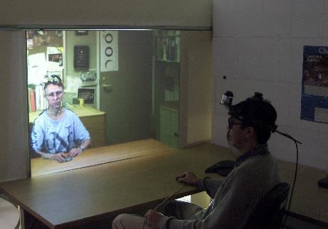
Telecubicle - 3D real time acquisition data
combined with static 3D background (latter is a laser scan of an office).
Remote participant Amela Sadagic
in
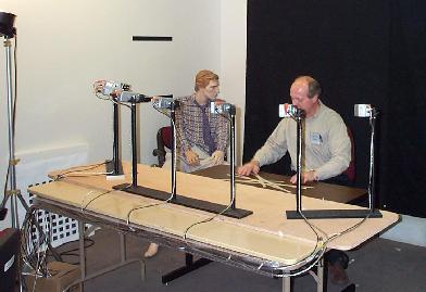
- Camera rig used for real-time 3D acquisition.
- Seven digital cameras arranged in semicircle.
- Each triple of neighboring cameras produces independent set of 3D data ("view"), so there are 5 "views" in total.
- The final 3D model is made by combining 5 views into one.
- MARS (Mobile Augmented Reality Systems)
- Aimed at exploring the synergy of two fields of user interface research:
- Augmented reality (AR), in which 3D displays are used to overlay a synthesized world on top of the real world,
- Reserarch focus :
- Identifying generic tasks a mobile user would want to carry out on a context aware computing system
- Defining a comprehensive set of re-usable user interface components for mobile augmented reality applications.
- Making combined use of different display technologies ranging from head-worn to hand-held to palm-top to best support a mobile user.
Prototype campus information system.
The user wears a backpack and headworn display,
and holds a handheld display and its stylus
- View shot through the see-through headworn display, showing campus buildings with overlaid names.
- Labels increase in brightness as they near the center of the display.
- After the
"Departments" menu item is selected, the department list for
the
- Selecting the "Departments" menu item causes an automatically-generated URL to be sent to the web browser on the handheld computer, containing the department list for the Philosophy Building.
- Actual home page for the English and Comparative Literature department, as selected from either the generated browser page or the department list in the augmented world.
Implementation Framework
- Hardware
- Backpack computer (with 3D graphics acceleration)
- Differential GPS system
- Head-worn display interface (with orientation tracker)
- Spread spectrum radio communication link
- The user also holds a small stylus-operated computer that can talk to the backpack computer via the spread spectrum radio channel.
- Use only off-the-shelf hardware
- Settled for items that were far bulkier than we would like them to be
e.g. a FieldWorks laptop
machine for the backpack computer, which offers us three PCI and three
EISA expansion slots (currently used among others for a powerful 3D graphics
adapter and a 6-serial port expansion card).
- Software
- Coterie prototyping environment that provides language-level support for distributed virtual environments.
- On the above hardware configuration the main mobile AR application running on the backpack computer receives continuous input from:
- the GPS system
- the orientation head tracker,
- the trackpad (mounted on the back of the handheld computer).
- It generates and displays at an interactive frame rate the overlaid 3D graphics and user interface components on the headworn display.