|
CS615 – Software Engineering I |
|
Lecture 4 |
Analysis Modeling (Chapter 8)
Requirements Analysis
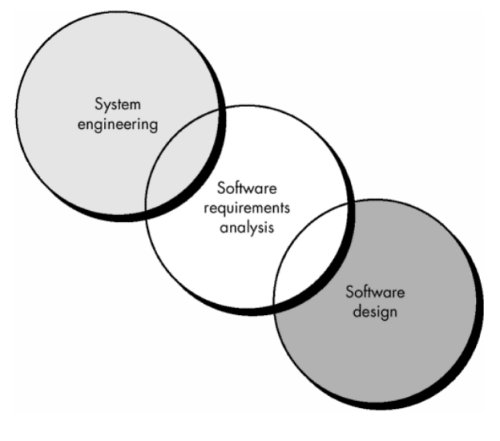
- Software engineering task that bridges the gap between system level requirements engineering and software design.
- Provides software designer with a representation of system information, function, and behavior that can be translated to data, architectural, and component-level designs.
- Expect to do a little bit of design during analysis and a little bit of analysis during design.
Software Requirements Analysis Phases
- Begins with System Specification and Software Project Plan
- Five Areas of effort
- Problem recognition
- Evaluation and synthesis (focus is on what not how)
- Modeling
- Specification
- Review
- Goal: recognition of the basic problem elements as perceived by the customer/users.
Software Requirements Elicitation
Process Initiation
- Customer meetings are the most commonly used technique.
- Use context free questions to find out:
- customer's goals and benefits
- identify stakeholders
- Who is behind the request for this work?
- Who will use the solution?
- What will be the economic benefit of a successful solution?
- Is there another source for the solution that you need?
- gain understanding of problem
- How would you characterize "good" output that would be generated by a successful solution?
- What problem(s) will this solution address?
- Can you show me (or describe) the environment in which the solution will be used?
- Will special performance issues or constraints affect the way the solution is approached?
- determine customer reactions to proposed solutions
- assess meeting effectiveness
- Are you the right person to answer these questions? Are your answers "official"?
- Are my questions relevant to the problem that you have?
- Am I asking too many questions?
- Can anyone else provide additional information?
- Should I be asking you anything else?
- Ensure that a representative cross section of users is interviewed.
Facilitated Action Specification Techniques (FAST)
- Creates a joint team of customers and developers to:
- identify the problem
- propose elements of the solution
- negotiate different approaches
- specify a preliminary set of solution requirements
- General Procedure
- Meeting held at neutral site, attended by both software engineers and customers.
- Rules established for preparation and participation.
- Agenda suggested to cover important points and to allow for brainstorming.
- Meeting controlled by facilitator (customer, developer, or outsider).
- Definition mechanism (flip charts, stickers, electronic device, etc.) is used.
- Goal is to identify problem, propose elements of solution, negotiate different approaches, and specify a preliminary set of solution requirements.
Quality Function Deployment (QFD)
- QFD emphasizes an understanding of what is valuable to the customer and then deploys these values throughout the engineering process
- Translates customer needs into technical software requirements.
- Uses customer interviews, observation, surveys, and historical data for requirements gathering.
- Customer voice table (contains summary of requirements)
- Normal requirements (must be present in product for customer to be satisfied)
- Expected requirements (things like ease of use or reliability of operation, that customer assumes will be present in a professionally developed product without having to request them explicitly)
- Exciting requirements (features that go beyond the customer's expectations and prove to be very satisfying when they are present)
- Function deployment (used during customer meetings to determine the value of each function required for system)
- Information deployment (identifies data objects and events produced and consumed by the system)
- Task deployment (examines the behavior of product within it environment)
- Value analysis (used to determine the relative priority of requirements during function, information, and task deployment)
Analysis Principles
Operational principles:
- The information domain of the problem must be represented and understood.
- The functions that the software is to perform must be defined.
- Software behavior must be represented.
- Models depicting information, function, and behavior must be partitioned in a hierarchical manner that uncovers detail.
- The analysis process should move from the essential information toward implementation detail.
Guiding principles:
- Understand the problem before you begin to create the analysis model.
- Develop prototypes that enable a user to understand how human/machine interaction will occur.
- Use multiple views of requirements. Building data, functional, and behavioral models provide the software engineer with three different views.
- Rank requirements.
- Work to eliminate ambiguity.
Information Domain
- Encompasses all data objects that contain numbers, text, images, audio, or video.
- Information content or data model (shows the relationships among the data and control objects that make up the system)
- Information flow (represents the manner in which data and control objects change as each moves through the system)
- Information structure (representations of the internal organizations of various data and control items)
Modeling
- Types:
- Data model (shows relationships among system objects)
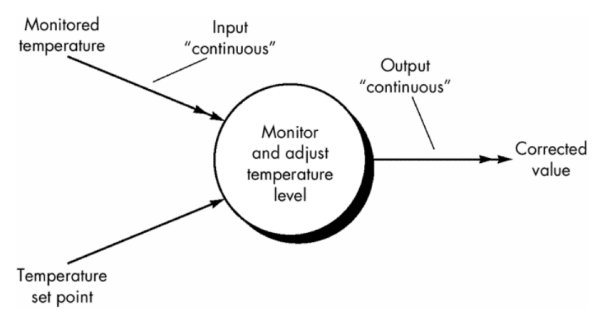
- Functional model (description of the functions that enable the transformations of system objects) - input - processing - output
- Behavioral model (manner in which software responds to events from the outside world)
- Importance:
- Aids the analyst in understanding the information, function, and behavior of a system
- Becomes the focal point for review and, therefore, the key to a determination of completeness, consistency, and accuracy of the specifications
- Foundation for design, providing the designer with an essential representation of software that can be "mapped" into an implementation context
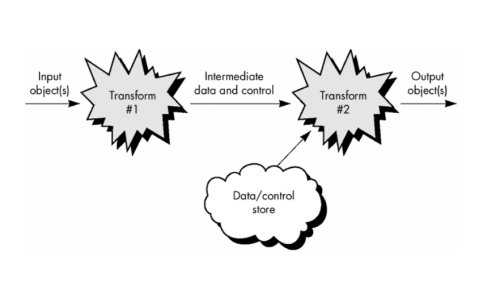
Information Flow
How data and control change as each moves through a system
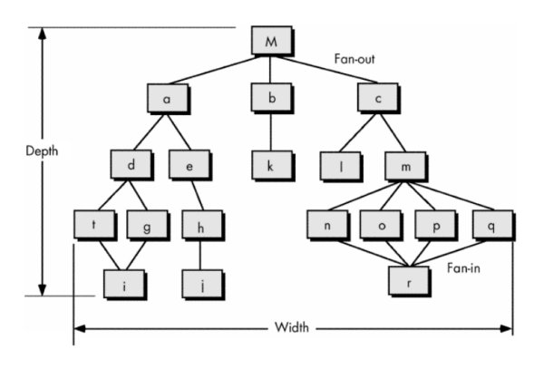
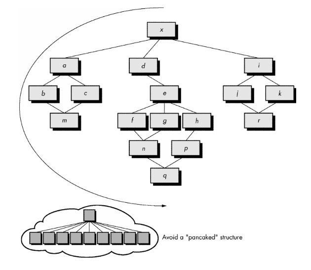
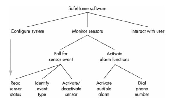
Partitioning
- Process that results in the elaboration of data, function, or behavior.
- Establish a hierarchical representation of function or information
- Partition the uppermost element by
- (1) exposing increasing detail by moving vertically in the hierarchy or
- (2) functionally decomposing the problem by moving horizontally in the hierarchy.
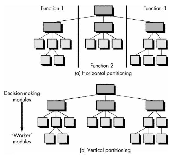
- Types:
- Horizontal partitioning is a breadth-first decomposition of the system function, behavior, or information, one level at a time.
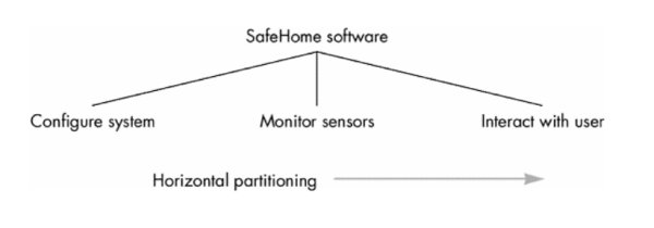
- Vertical partitioning is a depth-first elaboration of the system function, behavior, or information, one subsytem at a time.
Software Requirements Views
- Essential view - presents the functions to be accomplished and the information to be processed without regard to implementation.
- Implementation view - presents the real world manifestation of processing functions and information structures.
Software Prototyping
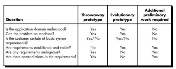
- Prototyping Paradigm
- Throwaway prototyping - prototype only used as a demonstration of product requirements, finished software is engineered using another paradigm
- Evolutionary prototyping - prototype is refined to build the finished system
- Issues
- Customer resources must be committed to evaluation and refinement of the prototype.
- Customer must be capable of making requirements decisions in a timely manner.
- Which Paradigm?
Prototyping Methods and Tools
- Fourth generation techniques - 4GT tools allow software engineer to generate executable code quickly
- Reusable software components - assembling prototype from a set of existing software components
- Formal specification and prototyping environments - can interactively create executable programs from software specification models
Specification Principles
- Separate functionality from implementation.
- Develop a behavioral model that describes functional responses to all system stimuli.
- Define the environment in which the system operates and indicate how the collection of agents will interact with it.
- Create a cognitive model rather than an implementation model.
- Recognize that the specification must be extensible and tolerant of incompleteness.
- Establish the content and structure of a specification so that it can be changed easily.
Specification Representation
- Representation format and content should be relevant to the problem.
- Information contained within the specification should be nested.
- Diagrams and other notational forms should be restricted in number and consistent in use.
- Representations should be revisable.
Specification Review
- Conducted by customer and software developer.
- Once approved, the specification becomes a contract for software development.
- The specification is difficult to test in a meaningful way.
- Assessing the impact of specification changes is hard to do.
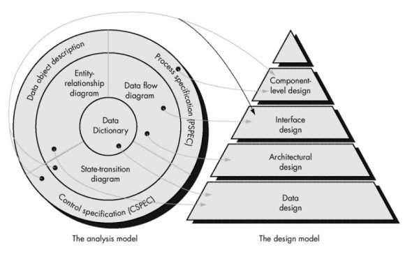
Analysis Model
- First technical representation of a system
- Combination of text and diagrams to represent software requirements (data, function, and behavior)
- Analysis models make it easier to uncover requirement inconsistencies and omissions.
- Two types of analysis modeling:
- structured analysis
- object-oriented analysis
- Data modeling: entity-relationship diagrams define data objects, attributes, and relationships.
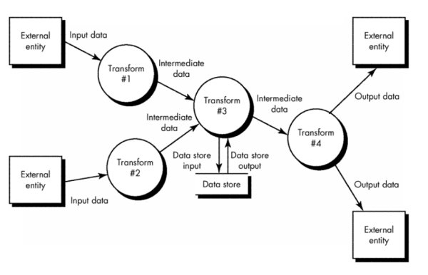
- Functional modeling: data flow diagrams show how data are transformed inside the system.
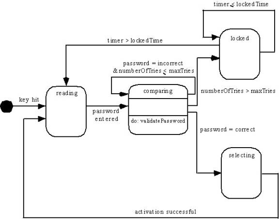
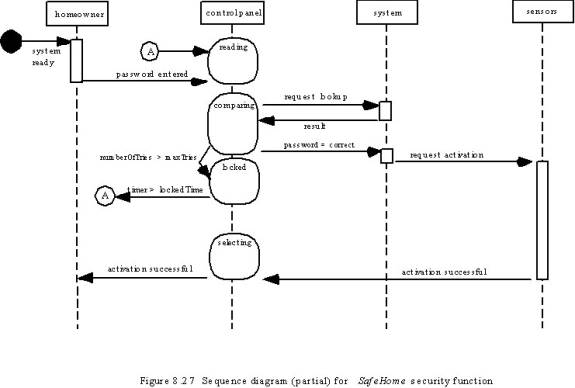
- Behavioral modeling: state transition diagrams show the impact of events.
Structured Analysis (DeMarco)
- Analysis products must be highly maintainable, especially the software requirements specification.
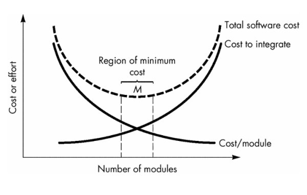
- Problems of size must be dealt with using an effective method of partitioning.
- Graphics should be used whenever possible.
- Differentiate between the logical (essential) and physical (implementation) considerations.
- Find something to help with requirements partitioning and document the partitioning before specification.
- Devise a way to track and evaluate user interfaces.
- Devise tools that describe logic and policy better than narrative text.
Analysis Model Objectives
- Describe what the customer requires.
- Establish a basis for the creation of a software design.
- Devise a set of requirements that can be validated once the software is built.
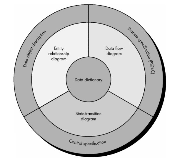
Analysis Model Elements
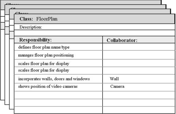
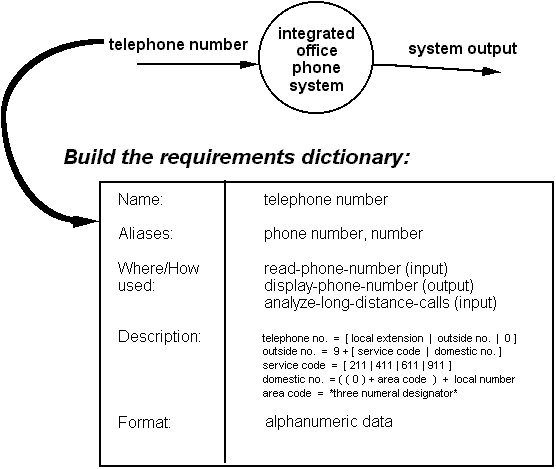
- Data dictionary - contains the descriptions of all data objects consumed or produced by the software
- Entity relationship diagram (ERD) - depicts relationships between data objects
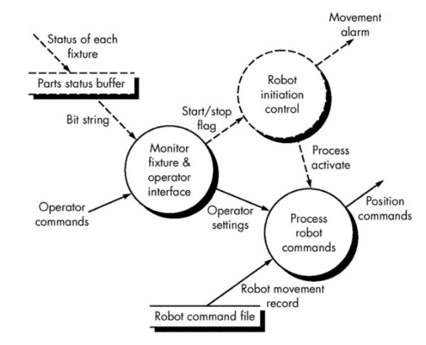
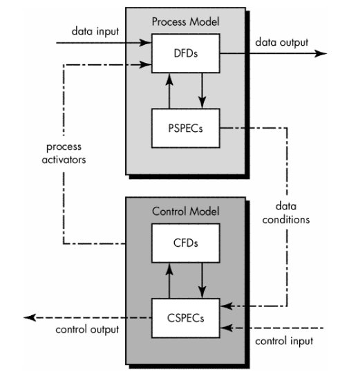
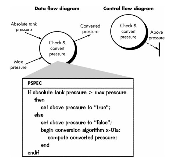
- Data flow diagram (DFD) - provides an indication of how data are transformed as they move through the system; also depicts functions that transform the data flow (a function is represented in a DFD using a process specification or PSPEC)
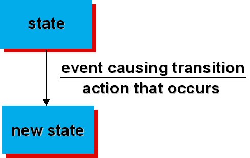
- State transition diagram (STD) - indicates how the system behaves as a consequence of external events, states are used to represent behavior modes. Arcs are labeled with the events triggering the transitions from one state to another (control information is contained in control specification or CSPEC)
Analysis Modeling: Where to Begin?
- A statement of scope can be acquired from:
- the FAST working document
- A set of use-cases
- the statement of scope must be “parsed” to extract data, function and behavioral domain information
- Statement of Scope
- Relatively brief description of the system to be built
- indicates data that are input and output and basic functionality
- indicates conditional processing (at a high level)
- implies certain constraints and limitations
- Identifying Objects and Operations
- define “objects” by underlining all nouns in the written statement of scope
- producers/consumers of data
- places where data are stored
- “composite” data items
- define “operations” by double underlining all active verbs
- processes relevant to the application
- data transformations
- consider other “services” that will be required by the objects
Data Modeling (ERD)
- Questions Answered
- What are the primary data objects to be processed by the system?
- What is the composition of each data object and what attributes describe the object?
- Where do the the objects currently reside?
- What are the relationships between each object and other objects?
- What are the relationships between the objects and the processes that transform them?
- Components
- Data object - any person, organization, device, or software product that produces or consumes information, e.g.
- report
- event
- place
- structure
- Attributes - name a data object instance, describe its characteristics, or make reference to another data object
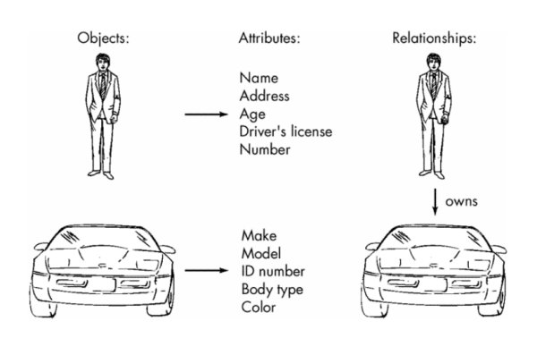
- Relationships - indicate the manner in which data objects are connected to one another
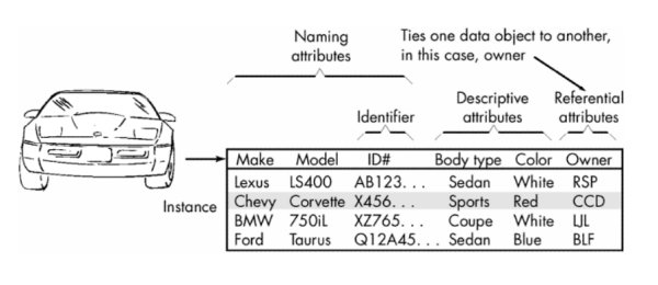
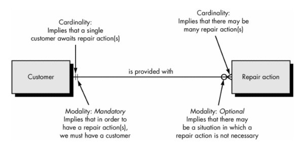
Cardinality and Modality (ERD)
- Cardinality - in data modeling, cardinality specifies how the number of occurrences of one object are related to the number of occurrences of another object (1:1, 1:N, M:N)
- Modality - zero (0) for an optional object relationship and one (1) for a mandatory relationship
Entity/Relationship Diagrams
- Primary components identified for the ERD:
- data objects
- attributes
- relationships
- type indicators
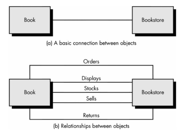
- Primary purpose: represent data objects and their relationships
- Iconography:
- Data objects are represented by a labeled rectangle
- Relationships are indicated with a labeled line connecting objects (Some variations: the connecting line contains a diamond that is labeled with the relationship)
- Connections between data objects and relationships are established using a variety of special symbols that indicate cardinality and modality
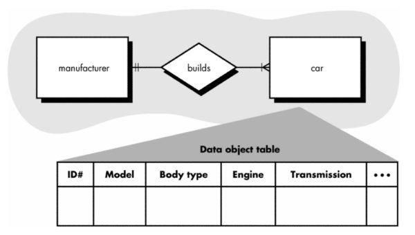
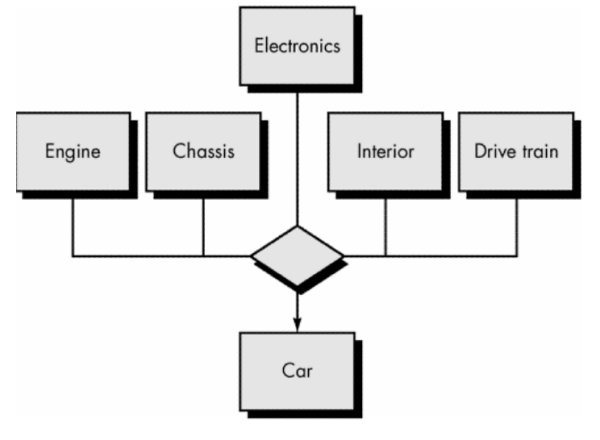
A simple ERD and data object table (Note: In this ERD the
relationship builds is indicated by a diamond)
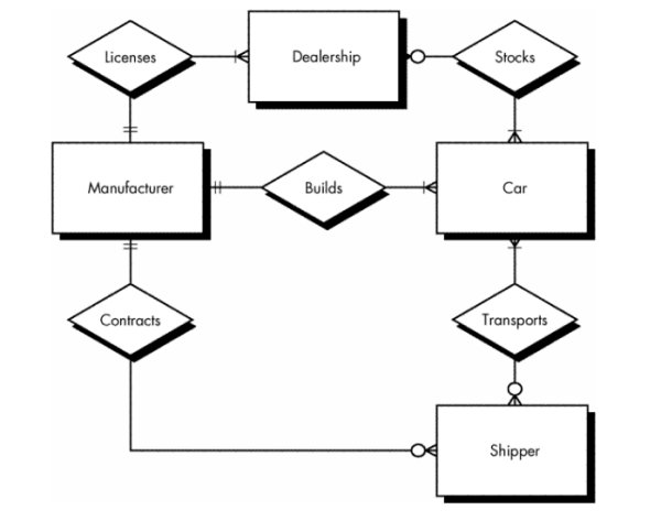
Expanded ERD
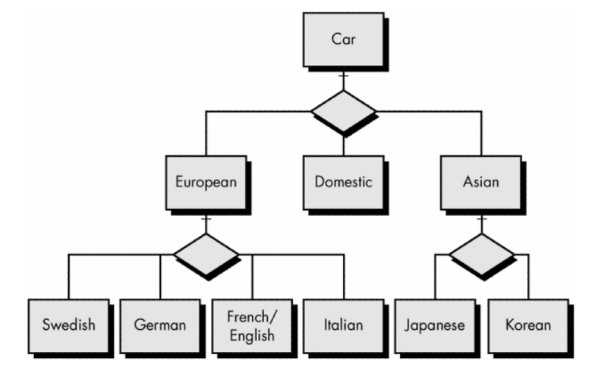
ERD representation of data object type hierarchies
Associative data object - represents the associativity between
objects
Creating Entity Relationship Diagrams
- During requirements elicitation, customers are asked to list the "things" that the application or business process addresses. These "things" evolve into a list of input and output data objects as well as external entities that produce or consume information.
- Taking the objects one at a time, the analyst and customer define whether or not a connection (unnamed at this stage) exists between the data object and other objects.
- Wherever a connection exists, the analyst and the customer create one or more object/relationship pairs.
- For each object/relationship pair, cardinality and modality are explored.
- Steps 2 through 4 are continued iteratively until all object/relationships have been defined. It is common to discover omissions as this process continues. New objects and relationships will invariably be added as the number of iterations grows.
- The attributes of each entity are defined.
- An entity relationship diagram is formalized and reviewed.
- Steps 1 through 7 are repeated until data modeling is complete.
Scenario-Based Modeling
Use-Cases
- Scenarios that describe how the product will be used in specific situations.
- Written narratives that describe the role of an actor (user or device) as interaction with the system occurs.
- Use-cases are designed from the actor's point of view.
- Not all actors can be identified during the first iteration of requirements elicitation, but it is important to identify the primary actors before developing the use-cases.
- Questions that should be answered by the use-case:
- What main tasks or functions are performed by the actor?
- What system information will the actor acquire, produce, or change?
- Will the actor have to inform the system about changes in the external environment?
- What information does the actor desire from the system?
- Does the actor wish to be informed about unexpected changes?
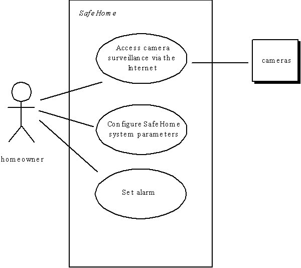
Use-Case Diagram
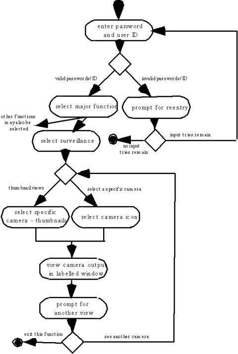
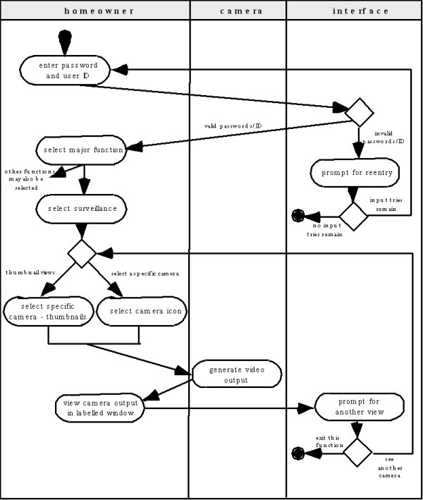
Activity Diagram
Supplements the use-case by
providing a diagrammatic representation of procedural flow