|
CS615 – Software Engineering I |
|
Lecture 4 |
Analysis Modeling (Chapter 8)
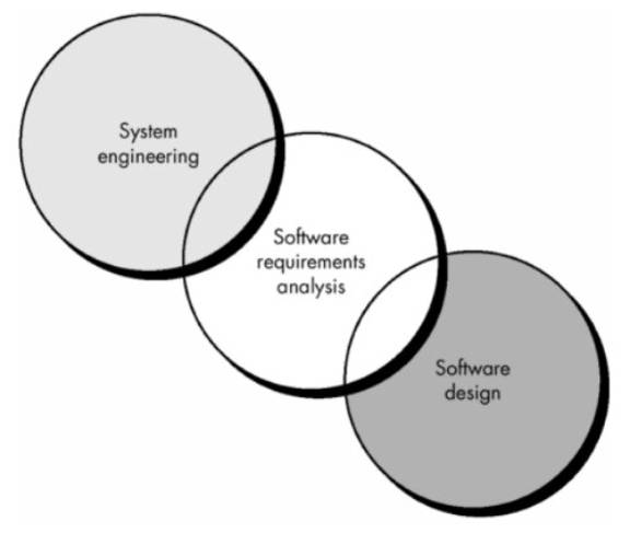
Requirements Analysis
- Software engineering task that bridges the gap between system level requirements engineering and software design.
- Provides software designer with a representation of system information, function, and behavior that can be translated to data, architectural, and component-level designs.
- Expect to do a little bit of design during analysis and a little bit of analysis during design.
Software Requirements Analysis Phases
- Begins with System Specification and Software Project Plan
- Five Areas of effort
- Problem recognition
- Evaluation and synthesis (focus is on what not how)
- Modeling
- Specification
- Review
- Goal: recognition of the basic problem elements as perceived by the customer/users.
Software Requirements Elicitation
Process Initiation
- Customer meetings are the most commonly used technique.
- Use context free questions to find out:
- customer's goals and benefits
- identify stakeholders
- Who is behind the request for this work?
- Who will use the solution?
- What will be the economic benefit of a successful solution?
- Is there another source for the solution that you need?
- gain understanding of problem
- How would you characterize "good" output that would be generated by a successful solution?
- What problem(s) will this solution address?
- Can you show me (or describe) the environment in which the solution will be used?
- Will special performance issues or constraints affect the way the solution is approached?
- determine customer reactions to proposed solutions
- assess meeting effectiveness
- Are you the right person to answer these questions? Are your answers "official"?
- Are my questions relevant to the problem that you have?
- Am I asking too many questions?
- Can anyone else provide additional information?
- Should I be asking you anything else?
- Ensure that a representative cross section of users is interviewed.
Facilitated Action Specification Techniques (FAST)
- Creates a joint team of customers and developers to:
- identify the problem
- propose elements of the solution
- negotiate different approaches
- specify a preliminary set of solution requirements
- General Procedure
- Meeting held at neutral site, attended by both software engineers and customers.
- Rules established for preparation and participation.
- Agenda suggested to cover important points and to allow for brainstorming.
- Meeting controlled by facilitator (customer, developer, or outsider).
- Definition mechanism (flip charts, stickers, electronic device, etc.) is used.
- Goal is to identify problem, propose elements of solution, negotiate different approaches, and specify a preliminary set of solution requirements.
Quality Function Deployment (QFD)
- QFD emphasizes an understanding of what is valuable to the customer and then deploys these values throughout the engineering process
- Translates customer needs into technical software requirements.
- Uses customer interviews, observation, surveys, and historical data for requirements gathering.
- Customer voice table (contains summary of requirements)
- Normal requirements (must be present in product for customer to be satisfied)
- Expected requirements (things like ease of use or reliability of operation, that customer assumes will be present in a professionally developed product without having to request them explicitly)
- Exciting requirements (features that go beyond the customer's expectations and prove to be very satisfying when they are present)
- Function deployment (used during customer meetings to determine the value of each function required for system)
- Information deployment (identifies data objects and events produced and consumed by the system)
- Task deployment (examines the behavior of product within it environment)
- Value analysis (used to determine the relative priority of requirements during function, information, and task deployment)
Analysis Principles
Operational principles:
- The information domain of the problem must be represented and understood.
- The functions that the software is to perform must be defined.
- Software behavior must be represented.
- Models depicting information, function, and behavior must be partitioned in a hierarchical manner that uncovers detail.
- The analysis process should move from the essential information toward implementation detail.
Guiding principles:
- Understand the problem before you begin to create the analysis model.
- Develop prototypes that enable a user to understand how human/machine interaction will occur.
- Use multiple views of requirements. Building data, functional, and behavioral models provide the software engineer with three different views.
- Rank requirements.
- Work to eliminate ambiguity.
Information Domain
- Encompasses all data objects that contain numbers, text, images, audio, or video.
- Information content or data model (shows the relationships among the data and control objects that make up the system)
- Information flow (represents the manner in which data and control objects change as each moves through the system)
- Information structure (representations of the internal organizations of various data and control items)
Modeling
- Types:
- Data model (shows relationships among system objects)
- Functional model (description of the functions that enable the transformations of system objects) - input - processing - output
- Behavioral model (manner in which software responds to events from the outside world)
- Importance:
- Aids the analyst in understanding the information, function, and behavior of a system
- Becomes the focal point for review and, therefore, the key to a determination of completeness, consistency, and accuracy of the specifications
- Foundation for design, providing the designer with an essential representation of software that can be "mapped" into an implementation context
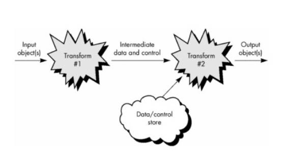
Information Flow
How data and control change as each moves through a system
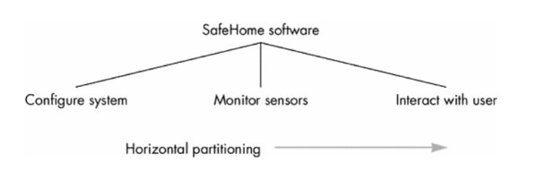
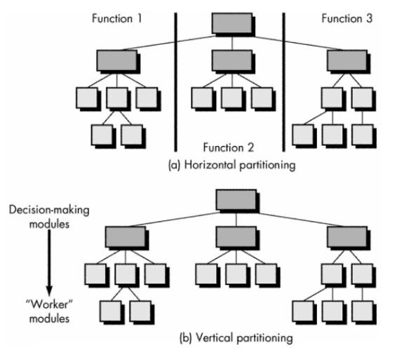
Partitioning
- Process that results in the elaboration of data, function, or behavior.
- Establish a hierarchical representation of function or information
- Partition the uppermost element by
- (1) exposing increasing detail by moving vertically in the hierarchy or
- (2) functionally decomposing the problem by moving horizontally in the hierarchy.
- Types:
- Horizontal partitioning is a breadth-first decomposition of the system function, behavior, or information, one level at a time.
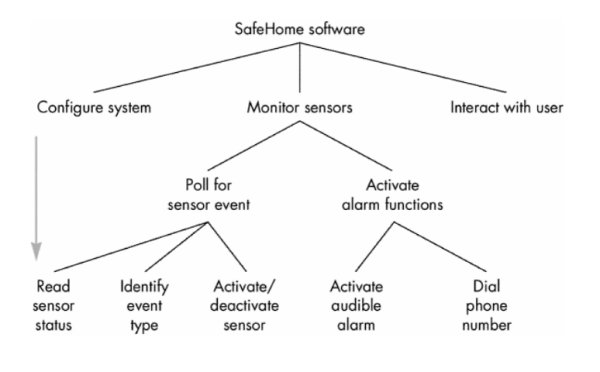
- Vertical partitioning is a depth-first elaboration of the system function, behavior, or information, one subsytem at a time.
Software Requirements Views
- Essential view - presents the functions to be accomplished and the information to be processed without regard to implementation.
- Implementation view - presents the real world manifestation of processing functions and information structures.
Software Prototyping
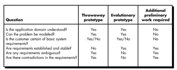
- Prototyping Paradigm
- Throwaway prototyping - prototype only used as a demonstration of product requirements, finished software is engineered using another paradigm
- Evolutionary prototyping - prototype is refined to build the finished system
- Issues
- Customer resources must be committed to evaluation and refinement of the prototype.
- Customer must be capable of making requirements decisions in a timely manner.
- Which Paradigm?
Prototyping Methods and Tools
- Fourth generation techniques - 4GT tools allow software engineer to generate executable code quickly
- Reusable software components - assembling prototype from a set of existing software components
- Formal specification and prototyping environments - can interactively create executable programs from software specification models
Specification Principles
- Separate functionality from implementation.
- Develop a behavioral model that describes functional responses to all system stimuli.
- Define the environment in which the system operates and indicate how the collection of agents will interact with it.
- Create a cognitive model rather than an implementation model.
- Recognize that the specification must be extensible and tolerant of incompleteness.
- Establish the content and structure of a specification so that it can be changed easily.
Specification Representation
- Representation format and content should be relevant to the problem.
- Information contained within the specification should be nested.
- Diagrams and other notational forms should be restricted in number and consistent in use.
- Representations should be revisable.
Specification Review
- Conducted by customer and software developer.
- Once approved, the specification becomes a contract for software development.
- The specification is difficult to test in a meaningful way.
- Assessing the impact of specification changes is hard to do.
Analysis Model
- First technical representation of a system
- Combination of text and diagrams to represent software requirements (data, function, and behavior)
- Analysis models make it easier to uncover requirement inconsistencies and omissions.
- Two types of analysis modeling:
- structured analysis
- object-oriented analysis
- Data modeling: entity-relationship diagrams define data objects, attributes, and relationships.
- Functional modeling: data flow diagrams show how data are transformed inside the system.
- Behavioral modeling: state transition diagrams show the impact of events.
Structured Analysis (DeMarco)
- Analysis products must be highly maintainable, especially the software requirements specification.
- Problems of size must be dealt with using an effective method of partitioning.
- Graphics should be used whenever possible.
- Differentiate between the logical (essential) and physical (implementation) considerations.
- Find something to help with requirements partitioning and document the partitioning before specification.
- Devise a way to track and evaluate user interfaces.
- Devise tools that describe logic and policy better than narrative text.
Analysis Model Objectives
- Describe what the customer requires.
- Establish a basis for the creation of a software design.
- Devise a set of requirements that can be validated once the software is built.
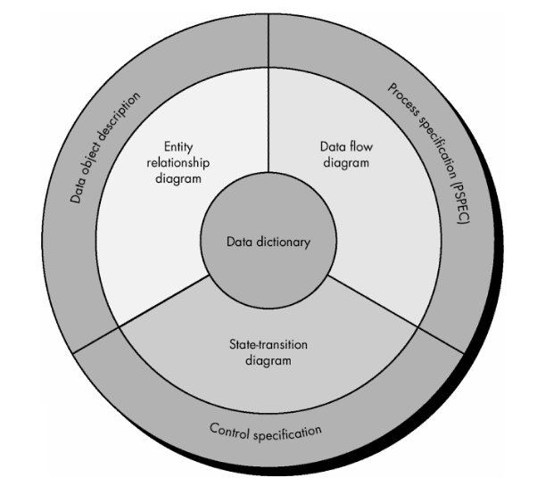
Analysis Model Elements
- Data dictionary - contains the descriptions of all data objects consumed or produced by the software
- Entity relationship diagram (ERD) - depicts relationships between data objects
- Data flow diagram (DFD) - provides an indication of how data are transformed as they move through the system; also depicts functions that transform the data flow (a function is represented in a DFD using a process specification or PSPEC)
- State transition diagram (STD) - indicates how the system behaves as a consequence of external events, states are used to represent behavior modes. Arcs are labeled with the events triggering the transitions from one state to another (control information is contained in control specification or CSPEC)
Analysis Modeling: Where to Begin?
- A statement of scope can be acquired from:
- the FAST working document
- A set of use-cases
- the statement of scope must be “parsed” to extract data, function and behavioral domain information
- Statement of Scope
- Relatively brief description of the system to be built
- indicates data that are input and output and basic functionality
- indicates conditional processing (at a high level)
- implies certain constraints and limitations
- Identifying Objects and Operations
- define “objects” by underlining all nouns in the written statement of scope
- producers/consumers of data
- places where data are stored
- “composite” data items
- define “operations” by double underlining all active verbs
- processes relevant to the application
- data transformations
- consider other “services” that will be required by the objects
Data Modeling (ERD)
- Questions Answered
- What are the primary data objects to be processed by the system?
- What is the composition of each data object and what attributes describe the object?
- Where do the the objects currently reside?
- What are the relationships between each object and other objects?
- What are the relationships between the objects and the processes that transform them?
- Components
- Data object - any person, organization, device, or software product that produces or consumes information, e.g.
- report
- event
- place
- structure
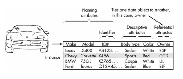
- Attributes - name a data object instance, describe its characteristics, or make reference to another data object
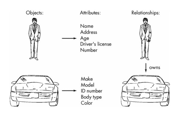
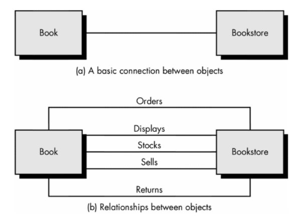
- Relationships - indicate the manner in which data objects are connected to one another
Cardinality and Modality (ERD)
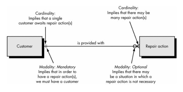
- Cardinality - in data modeling, cardinality specifies how the number of occurrences of one object are related to the number of occurrences of another object (1:1, 1:N, M:N)
- Modality - zero (0) for an optional object relationship and one (1) for a mandatory relationship
Entity/Relationship Diagrams
- Primary components identified for the ERD:
- data objects
- attributes
- relationships
- type indicators
- Primary purpose: represent data objects and their relationships
- Iconography:
- Data objects are represented by a labeled rectangle
- Relationships are indicated with a labeled line connecting objects (Some variations: the connecting line contains a diamond that is labeled with the relationship)
- Connections between data objects and relationships are established using a variety of special symbols that indicate cardinality and modality
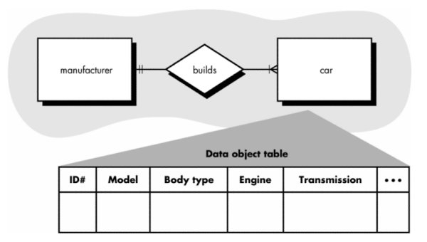
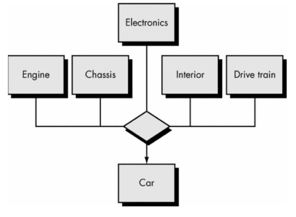
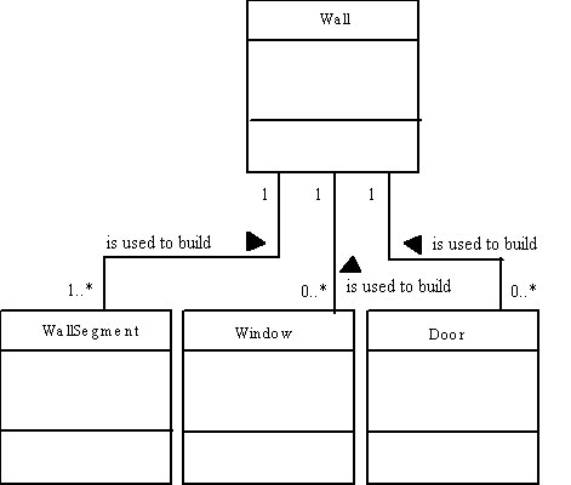
A simple ERD and data object table (Note: In this ERD the
relationship builds is indicated by a diamond)
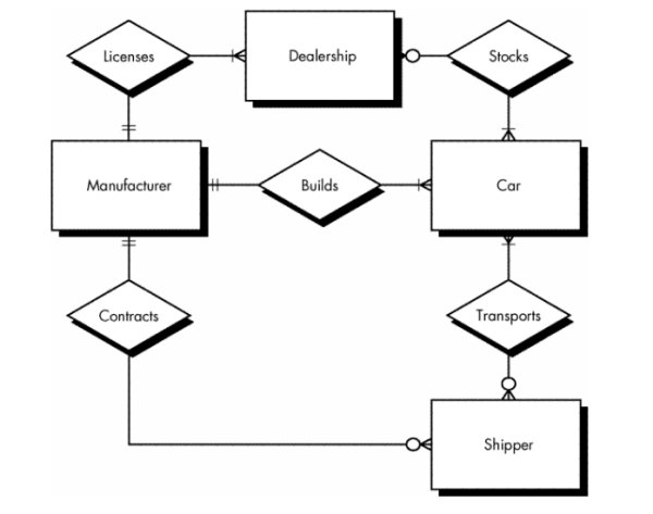
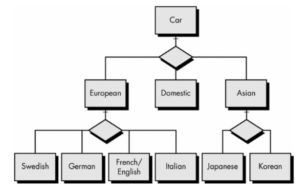
Expanded ERD
ERD representation of data object type hierarchies
Associative data object - represents the associativity between
objects
Creating Entity Relationship Diagrams
- During requirements elicitation, customers are asked to list the "things" that the application or business process addresses. These "things" evolve into a list of input and output data objects as well as external entities that produce or consume information.
- Taking the objects one at a time, the analyst and customer define whether or not a connection (unnamed at this stage) exists between the data object and other objects.
- Wherever a connection exists, the analyst and the customer create one or more object/relationship pairs.
- For each object/relationship pair, cardinality and modality are explored.
- Steps 2 through 4 are continued iteratively until all object/relationships have been defined. It is common to discover omissions as this process continues. New objects and relationships will invariably be added as the number of iterations grows.
- The attributes of each entity are defined.
- An entity relationship diagram is formalized and reviewed.
- Steps 1 through 7 are repeated until data modeling is complete.
Scenario-Based
Modeling
Use-Cases
- Scenarios that describe how the product will be used in specific situations.
- Written narratives that describe the role of an actor (user or device) as interaction with the system occurs.
- Use-cases are designed from the actor's point of view.
- Not all actors can be identified during the first iteration of requirements elicitation, but it is important to identify the primary actors before developing the use-cases.
- Questions that should be answered by the use-case:
- What main tasks or functions are performed by the actor?
- What system information will the actor acquire, produce, or change?
- Will the actor have to inform the system about changes in the external environment?
- What information does the actor desire from the system?
- Does the actor wish to be informed about unexpected changes?
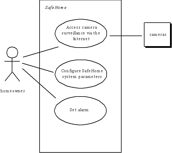
Use-Case Diagram
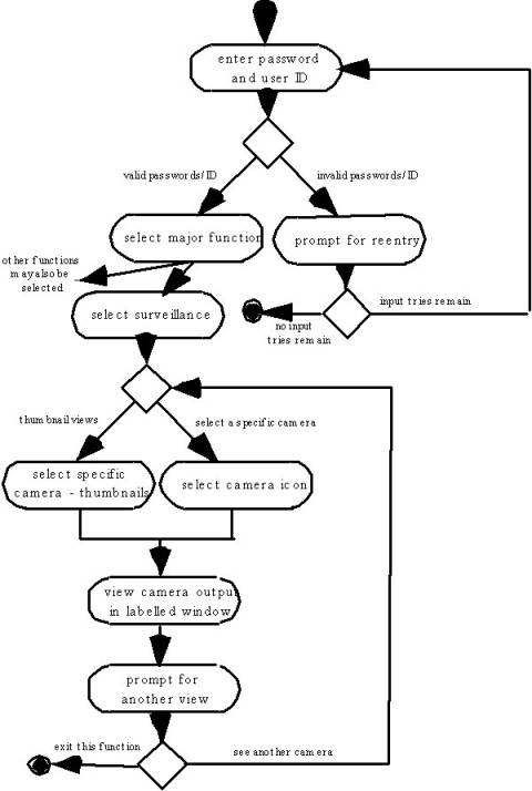
Activity Diagram
Supplements the use-case by
providing a diagrammatic representation of procedural flow
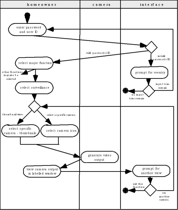
Swimlane Diagrams
Allows the modeler to:
- represent the flow of activities described by
the use-case
- indicate which actor (if there are multiple
actors involved in a specific use-case) or analysis class has
responsibility for the action described by an activity rectangle
Flow-Oriented
Modeling
Functional Modeling and
Information Flow (DFD)
- Shows the relationships of external entities, process or transforms, data items, and data stores
- DFD's cannot show procedural detail (e.g. conditionals or loops) only the flow of data through the software
- Refinement from one DFD level to the next should follow approximately a 1:5 ratio (this ratio will reduce as the refinement proceeds)
- To model real-time systems, structured analysis notation must be available for time continuous data and event processing
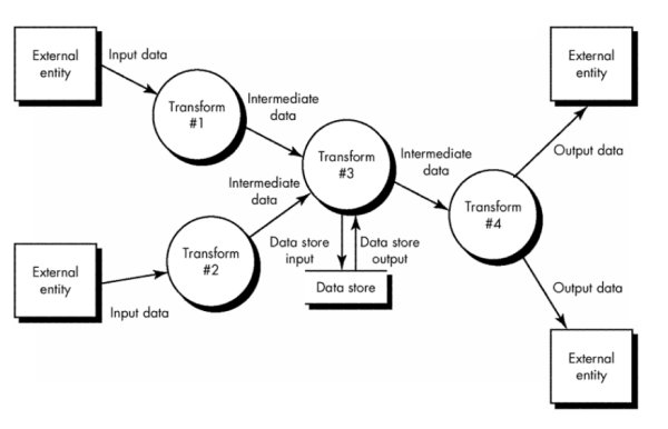
Data Flow Diagrams (DFDs)
- Graphical representation that depicts information flow and the transforms that are applied as data move from input to output
- Represents a system or software at any level of abstraction
- Partitioned into levels that represent increasing information flow and functional detail - satisfies the second operational analysis principle (i.e., creating a functional model)
- Iconography
- Circle (aka bubble) : a process or transform applied to data and changes it in some way
- Arrow : one or more data items (data objects)
- Double line: data store — stored information that is used by the software
- Shadowed Rectangle : data source or sink - where data begins or ends
- Creating Data Flow Diagram
- Level 0 data flow diagram should depict the system as a single bubble
- Primary input and output should be carefully noted
- Refinement should begin by consolidating candidate processes, data objects, and data stores to be represented at the next level
- Label all arrows with meaningful names
- Information flow must be maintained from one level to level
- Refine one bubble at a time
- Write a PSPEC (a "mini-spec" written using English or another natural language or a program design language) for each bubble in the final DFD
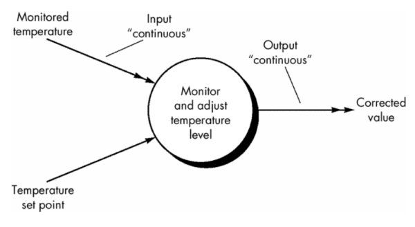
- Extensions for Real-Time Systems
- Conventional data flow notation does not make a distinction between discrete data and time-continuous data
- Ward and Mellor Extensions - mechanism for representing time-continuous data flow
- Information flow is gathered or produced on a time-continuous basis
- Control information is passed throughout the system and associated control processing
- Multiple instances of the same transformation are sometimes encountered in multitasking situations
- Systems have states and a mechanism causes transition between states
- Initial Iconography
- double headed arrow is used to represent time-continuous flow
- single headed arrow is used to indicate discrete data flow
- Revised Iconography
- Data flow is represented using a solid arrow
- Control flow is represented using a dashed or shaded arrow
- Control process - handles only control flows - represented as a dashed bubble
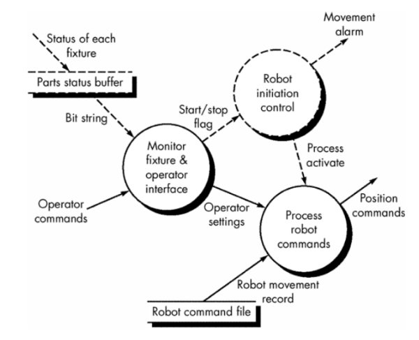
- Hatley and Pirbhai Extensions
- Focus on the representation and specification of the control-oriented aspects of the software
- Dashed arrow used to represent control or event flow
- Dashed and solid notation be represented separately - control flow diagram
- Control flow diagram CFD - shows control flow, rather than data flow
- Notational reference (a solid bar) to a control specification (CSPEC) is used
- CSPEC used to indicate:
- how the software behaves when an event or control signal is sensed
- which processes are invoked as a consequence of the occurrence of the event
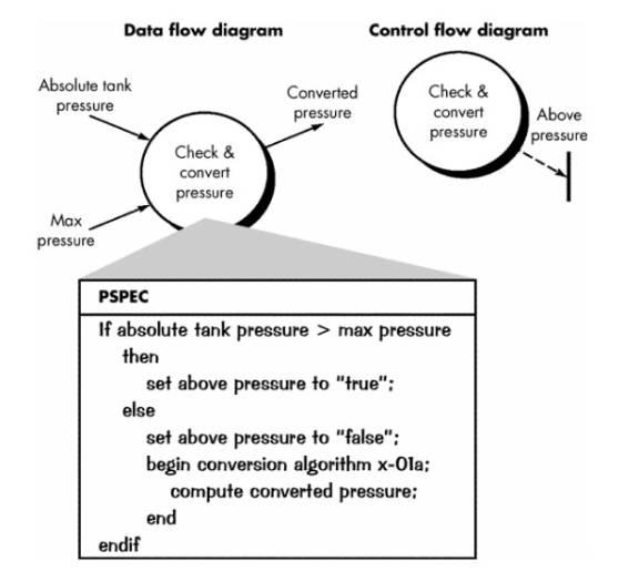
- A process specification is used to describe the inner workings of a process represented in a flow diagram
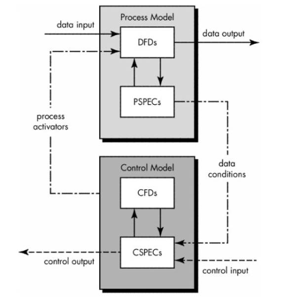
- Hatley and Pirbhai's model of a real-time system
- Data flow diagrams used to represent data and the processes that manipulate it.
- Control flow diagrams show how events flow among processes and illustrate those external events that cause various processes to be activated
The relationship between data and control models
- Creating Control Flow Diagrams
- Begin by stripping all the data flow arrows form the DFD
- Events (solid arrows) and control items (dashed arrows) are added to the diagram
- Add a window to the CSPEC (contains an STD that is a sequential specification of the behavior) for each bubble in the final CFD
Class-Based
Modeling
- Identify analysis
classes by examining the problem statement
- Use a “grammatical
parse” to isolate potential classes
- Identify the
attributes of each class
- Identify operations
that manipulate the attributes
Analysis Classes
- External entities (e.g., other systems, devices, people) that
produce or consume information to be used by a computer-based system.
- Things (e.g, reports, displays, letters, signals) that
are part of the information domain for the problem.
- Occurrences or
events (e.g., a property
transfer or the completion of a series of robot movements) that occur
within the context of system operation.
- Roles (e.g., manager, engineer, salesperson) played
by people who interact with the system.
- Organizational
units (e.g., division, group,
team) that are relevant to an application.
- Places (e.g., manufacturing floor or loading dock) that
establish the context of the problem and the overall function of the
system.
- Structures (e.g., sensors, four-wheeled vehicles, or
computers) that define a class of objects or related classes of objects.
Selecting Classes—Criteria
- retained information
- needed services
- multiple attributes
- common attributes
- common operations
- essential requirements
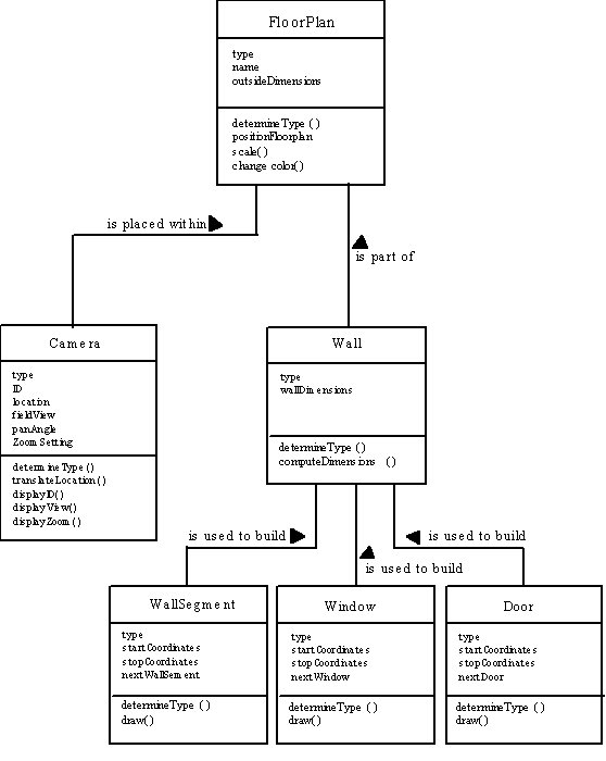
Class Diagram
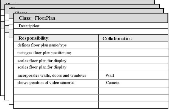
CRC Modeling
- Analysis classes have
“responsibilities”
- Responsibilities are the attributes and operations encapsulated
by the class
- Analysis classes
collaborate with one another
- Collaborators are those classes that are required to provide
a class with the information needed to complete a responsibility.
- In general, a
collaboration implies either a request for information or a request for
some action.
Class
Types
- Entity classes, also called model or business
classes, are extracted directly from the statement of the problem (e.g.,
FloorPlan and Sensor).
- Boundary
classes are used to create
the interface (e.g., interactive screen or printed reports) that the user
sees and interacts with as the software is used.
- Controller
classes manage a “unit of work” [UML03] from start to
finish.
controller classes can be designed to manage
- the creation or
update of entity objects;
- the instantiation
of boundary objects as they obtain information from entity objects;
- complex
communication between sets of objects;
- validation of data
communicated between objects or between the user and the application.
Class Responsibilities
·
System
intelligence should be distributed across classes to best address the needs of
the problem
·
Each
responsibility should be stated as generally as possible
·
Information
and the behavior related to it should reside within the same class
·
Information
about one thing should be localized with a single class, not distributed across
multiple classes.
·
Responsibilities
should be shared among related classes, when appropriate.
Class
Colaborations
- Classes fulfill their
responsibilities in one of two ways:
- A class can use its
own operations to manipulate its own attributes, thereby fulfilling a
particular responsibility, or
- a class can
collaborate with other classes.
- Collaborations
identify relationships between classes
- Collaborations are
identified by determining whether a class can fulfill each responsibility
itself
- three different
generic relationships between classes :
- the is-part-of relationship
- the has-knowledge-of
relationship
- the depends-upon
relationship
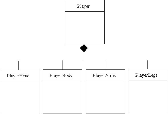
Composite Aggregate Class
Reviewing the CRC Model
- All participants in
the review (of the CRC model) are given a subset of the CRC model index
cards.
- Cards that
collaborate should be separated (i.e., no reviewer should have two cards
that collaborate).
- All use-case scenarios (and corresponding use-case diagrams) should be organized into categories.
- The review leader
reads the use-case deliberately.
- As the review
leader comes to a named object, she passes a token to the person holding
the corresponding class index card.
- When the token is
passed, the holder of the class card is asked to describe the
responsibilities noted on the card.
- The group determines
whether one (or more) of the responsibilities satisfies the use-case
requirement.
- If the
responsibilities and collaborations noted on the index cards cannot
accommodate the use-case, modifications are made to the cards.
- This may include the definition of new classes (and corresponding CRC index cards) or the specification of new or revised responsibilities or collaborations on existing cards.
Associations and Dependencies
- Two analysis classes
are often related to one another in some fashion
- In UML these
relationships are called associations
- Associations can be
refined by indicating multiplicity (the term cardinality is
used in data modeling
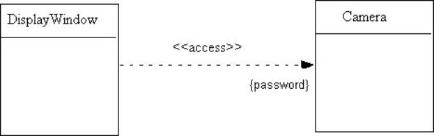
- In many instances, a
client-server relationship exists between two analysis classes.
- In such cases, a
client-class depends on the server-class in some way and a dependency
relationship is established
Multiciplicity
Dependencies
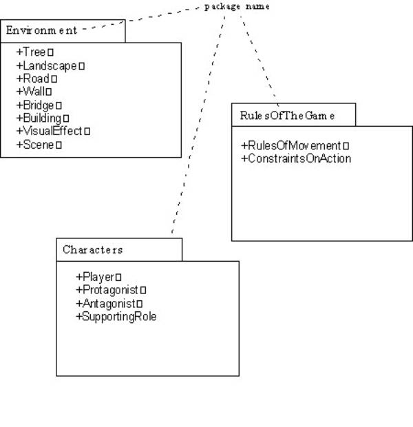
Analysis Packages
- Various elements of
the analysis model (e.g., use-cases, analysis classes) are categorized in
a manner that packages them as a grouping
- The plus sign
preceding the analysis class name in each package indicates that the
classes have public visibility and are therefore accessible from other
packages.
- Other symbols can
precede an element within a package. A minus sign indicates that an
element is hidden from all other packages and a # symbol indicates that an
element is accessible only to packages contained within a given package.
Behavioral
Modeling
· The behavioral model indicates how software will respond to external events or stimuli.
- To create the model,
the analyst must perform the following steps:
·
Evaluate
all use-cases to fully understand the sequence of interaction within the
system.
·
Identify
events that drive the interaction sequence and understand how these events
relate to specific objects.
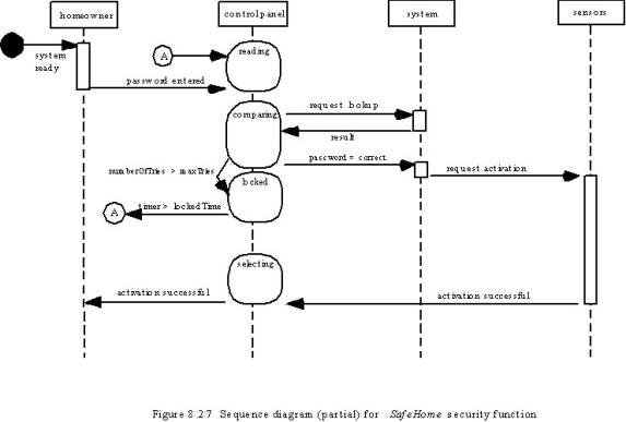
·
Create
a sequence for each use-case.
·
Build
a state diagram for the system.
·
Review
the behavioral model to verify accuracy and consistency.
- In the context of
behavioral modeling, two different characterizations of states must be
considered:
- the state of each
class as the system performs its function and
- the state of the system as observed from the outside as the system performs its function
- The state of a class
takes on both passive and active characteristics.
- A passive state
is simply the current status of all of an object’s attributes.
- The active state
of an object indicates the current status of the object as it undergoes a
continuing transformation or processing.
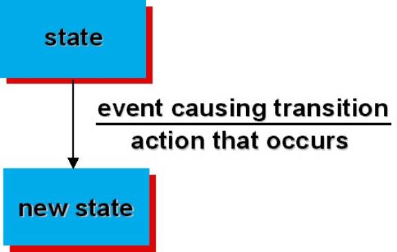
- State transition diagrams represent the system states and events that trigger state transitions
- state—a set of observable circum-stances that characterizes the behavior of a system at a given time
- state transition—the movement from one state to another
- event—an occurrence that causes the system to exhibit some predictable form of behavior
- action—process that occurs as a consequence of making a transition
- STD's indicate actions (e.g. process activation) taken as a consequence of a particular event
- A state is any observable mode of behavior
State Diagram for the ControlPanel Class
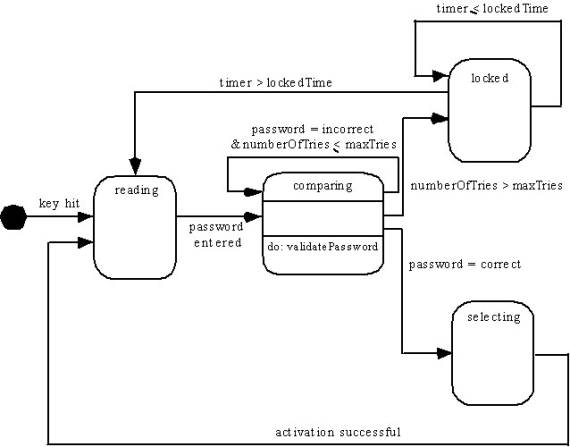
- Hatley and Pirbhai control flow diagrams (CFD) can also be used for behavioral modeling
- Iconography
- Rectangles represent system states
- Arrows represent transitions between states
- Each arrow is labeled with a ruled expression
- Top value - the event(s) that cause the transition to occur
- Bottom value - the action that occurs as a consequence of the event
Example
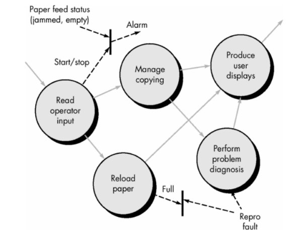
Level 1 CFD for photocopier software
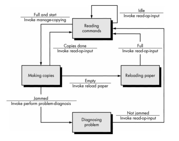
State transition diagram for photocopier software
- Building a Behavioral Model
- make a list of the different states of a system (How does the system behave?)
- indicate how the system makes a transition from one state to another (How does the system change state?)
- indicate event
- indicate action
- draw a state transition diagram
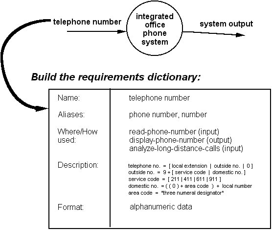
Data Dictionary Contents
Data dictionary is an organized listing of all data elements that are pertinent to the system, with precise, rigorous definitions so that both user and system analyst will have a common understanding of inputs, outputs, components of stores and [even] intermediate calculations
- Name - primary name for each data or control item, data store, or external entity
- Alias - alternate names for each data object
- Where-used/how-used - a listing of processes that use the data or control item and how it is used (e.g. input to process, output from process, as a store, as an external entity)
- Content description - notation for representing content
- Supplementary information - other data type information, preset values, restrictions, limitations, etc.
Notation
|
Data Construct |
Notation |
Meaning |
|
|
= |
is composed of |
|
Sequence |
+ |
and |
|
Selection |
[ | ] |
either-or |
|
Repetition |
{}n |
n repetitions of |
|
|
( ) |
optional data |
|
|
* ... * |
delimits comments |
Notation enables representation of composite data in one of the three fundamental ways that it can be constructed:
- As a sequence of data items.
- As a selection from among a set of data items.
- As a repeated grouping of data items. Each data item entry that is represented as part of a sequence, selection, or repetition may itself be another composite data item that needs further refinement within the dictionary.
Design Engineering (Chapter 9)
- Software requirements model is transformed into design models that describe the details of the data structures, system architecture, interface, and components
- Each design product is reviewed for quality before moving to the next phase of software development
Translating the analysis model into a software design
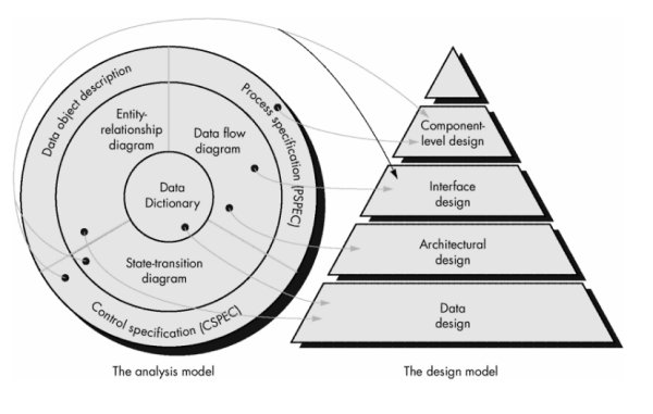
Design Specification Models
- Data design - created by transforming the analysis information model (data dictionary and ERD) into data structures required to implement the software
- Architectural design - defines the relationships among the major structural elements of the software, it is derived from the system specification, the analysis model, and the subsystem interactions defined in the analysis model (DFD)
- Interface design - describes how the software elements communicate with each other, with other systems, and with human users; the data flow and control flow diagrams provide much the necessary information
- Component-level design - created by transforming the structural elements defined by the software architecture into procedural descriptions of software components using information obtained from the PSPEC, CSPEC, and STD
The Design Process
- Good Design Characteristics
- The design must implement all of the explicit requirements contained in the analysis model, and it must accommodate all of the implicit requirements desired by the customer.
- The design must be a readable, understandable guide for those who generate code and for those who test and subsequently support the software.
- The design should provide a complete picture of the software, addressing the data, functional, and behavioral domains from an implementation perspective.
- Design Guidelines
1. A design should exhibit an architectural structure that it:
(1) has been created using recognizable design
patterns
(2) is composed of components that exhibit good
design characteristics
(3) can be implemented in an evolutionary
fashion, thereby facilitating implementation and testing.
2. A design should be modular; that is, the software should be logically partitioned into elements that perform specific functions and subfunctions.
3. A design should contain distinct representations of data, architecture, interfaces, and components (modules).
4. A design should lead to data structures that are appropriate for the objects to be implemented and are drawn from recognizable data patterns.
5. A design should lead to components that exhibit independent functional characteristics.
6. A design should lead to interfaces that reduce the complexity of connections between modules and with the external environment.
7. A design should be derived using a repeatable method that is driven by information obtained during software requirements analysis.
Design Principles
- The design process should not suffer from "tunnel vision."
- The design should be traceable to the analysis model.
- The design should not reinvent the wheel.
- The structure of the software design should mimic the structure of the problem domain.
- The design should exhibit uniformity and integration.
- The design should be structured to accommodate change.
- The design should be structured to degrade gently, even when aberrant data, events, or operating conditions are encountered.
- Design is not coding, coding is not design.
- The design should be assessed for quality as it is being created, not after the fact.
- The design should be reviewed to minimize conceptual (semantic) errors.
Software Design Concepts
- Abstraction - allows designers to focus on solving a problem without being concerned about irrelevant lower level details (procedural abstraction - named sequence of events, data abstraction - named collection of data objects)
- Refinement - process of elaboration where the designer provides successively more detail for each design component
- Modularity - the degree to which software can be understood by examining its components independently of one another
Modularity and software cost
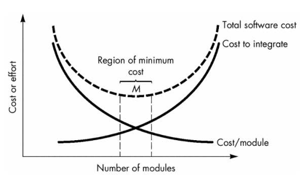
- Modular Design Method Evaluation Criteria
- Modular decomposability - provides systematic means for breaking problem into subproblems
- Modular composability - supports reuse of existing modules in new systems
- Modular understandability - module can be understood as a stand-alone unit
- Modular continuity - side-effects due to module changes minimized
- Modular protection - side-effects due to processing errors minimized
- Software architecture - overall structure of the software components and the ways in which that structure provides conceptual integrity for a system
- Structural properties - Defines the components of a system (e.g., modules, objects, filters) and the manner in which those components are packaged and interact with one another.
- Extra-functional properties - The architectural design description should address how the design architecture achieves requirements for performance, capacity, reliability, security, adaptability, and other system characteristics.
- Families of related systems - The architectural design should draw upon repeatable patterns that are commonly encountered in the design of families of similar systems. In essence, the design should have the ability to reuse architectural building blocks.
- Control hierarchy or program structure - represents the module organization and implies a control hierarchy, but does not represent the procedural aspects of the software (e.g. event sequences)
Typical Hierarchical Control Structure
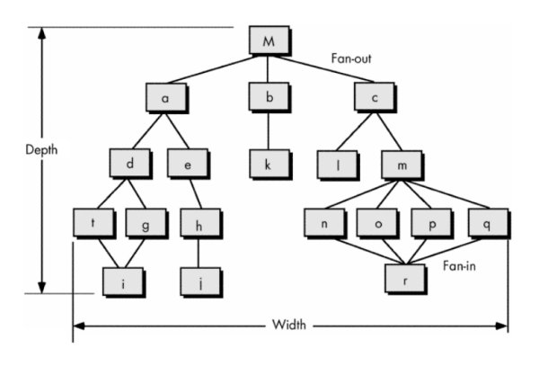
- Structural partitioning
- horizontal partitioning - defines three partitions (input, data transformations, and output)
- Benefits:
- software that is easier to test
- software that is easier to maintain
- propagation of fewer side effects
- software that is easier to extend
- vertical partitioning (factoring) - distributes control in a top-down manner (control decisions in top level modules and processing work in the lower level modules)
- Data structure - representation of the logical relationship among individual data elements (requires at least as much attention as algorithm design)
- Software procedure - precise specification of processing (event sequences, decision points, repetitive operations, data organization/structure)
- Information hiding - information (data and procedure) contained within a module is inaccessible to modules that have no need for such information
Effective Modular Design
Functional
Independence
- Design software so that each module addresses a specific subfunction of requirements and has a simple interface when viewed from other parts of the program structure
- Measured using two qualitative criteria:
- Cohesion is a measure of the relative functional strength of a module
- Natural extension of the information hiding
- Cohesive module performs a single task within a software procedure, requiring little interaction with procedures being performed in other parts of a program
- Range of Cohesion - low (worse) to high (better)
|
low |
coincidental cohesion |
module that performs tasks that are related logically |
|
|
temporal cohesion |
module contains tasks that are related by the fact that all must be executed with the same spanof time |
|
|
procedural cohesion |
processing elements of a module are related and must be executed in a specific order |
|
|
communicational cohesion |
all processingelements concentrate on one area of a data structure |
|
high |
|
module that performs one distinctprocedural task. |
- Coupling is a measure of the relative interdependence among modules
- Best - lowest possible coupling
|
low |
data coupling |
simple data are passed- a one-to-one correspondence of items exists |
|
|
stamp coupling |
a portion of a datastructure (rather than simple arguments) is passed via a module interface |
|
|
control coupling |
where a "control flag" is passed between modules |
|
|
external coupling |
modules are tied toan environment external to software |
|
|
common coupling |
when a number of modulesreference a global data area |
|
high |
content coupling |
when one modulemakes use of data or control information maintained within the boundaryof another module |
Design Heuristics for effective Modularity
Program structure can be manipulated according to the following set of heuristics:
- Evaluate the "first iteration" of the program structure to reduce coupling and improve cohesion
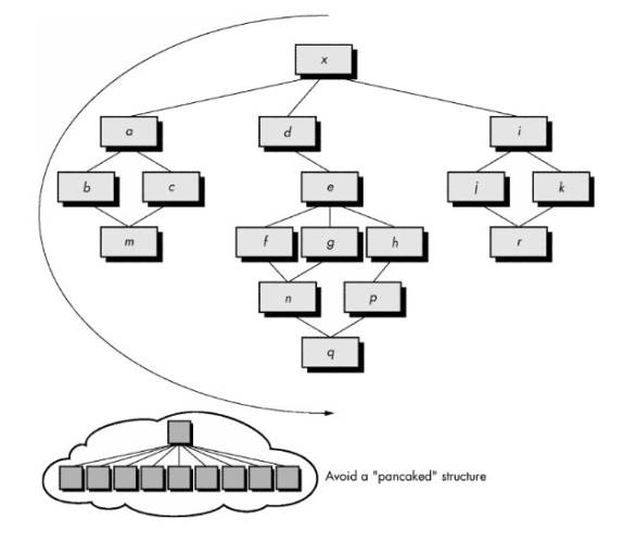
- Attempt to minimize structures with high fan-out; strive for fan-in as depth increases
- Keep the scope of effect of a module within the scope of control of that module
- Evaluate module interfaces to reduce complexity and redundancy and improve consistency
- Define modules whose function is predictable, but avoid modules that are overly restrictive
- Strive for "controlled entry" modules by avoiding "pathological connections."
Design Documentation
Software Design Specification from:
- System Specification
- Software Requirements Specification