|
CS615 – Software Engineering I |
|
Lecture 5 |
Architectural Design (Chapter 10)
What Is Architecture?
Software architecture is a representation that enables a software engineer to
- Analyze the effectiveness of the design in meeting stated requirements
- Consider architectural alternatives
- Reduce the risk associated with the construction of the software
- Examine the system as a whole
Why Is Architecture Important?
- Enable communication between all parties (stakeholders) interested in the development of a computer-based system.
- Highlights early design decisions that will have a profound impact on all software engineering work that follows and on the ultimate success of the system as an operational entity.
- Architecture "constitutes a relatively small, intellectually graspable model of how the system is structured and how its components work together".
Data Design
- refine data objects and develop a set of data abstractions
- implement data object attributes as one or more data structures
- review data structures to ensure that appropriate relationships have been established
- simplify data structures as required
Data Design Principles
- Systematic analysis principles applied to function and behavior should also be applied to data.
- All data structures and the operations to be performed on each should be identified.
- Data dictionary should be established and used to define both data and program design.
- Low level design processes should be deferred until late in the design process.
- Representations of data structure should be known only to those modules that must make direct use of the data contained within in the data structure.
- A library of useful data structures and operations should be developed.
- A software design and its implementation language should support the specification and realization of abstract data types.
Architectural Styles
Each style describes a system category that encompasses:
- a set of components (e.g., a database, computational modules) that perform a function required by a system
- a set of connectors that enable “communication, coordination and cooperation” among components
- constraints that define how components can be integrated to form the system
- semantic models that enable a designer to understand the overall properties of a system by analyzing the known properties of its constituent parts.
- Data centered - data store (e.g. file or database) lies at the center of this architecture and is accessed frequently by other components that modify data

- Data flow - input data is transformed by a series of computational or manipulative components into output data

- Call and return - program structure decomposes function into control hierarchy with main program invokes several subprograms
- Main program/subprogram architectures: Classic program structure decomposes function into a control hierarchy where a "main" program invokes a number of program components, which in turn may invoke still other components.
- Remote procedure call architectures: Components of a main program/subprogram architecture are distributed across multiple computers on a network
- Object-oriented - components of system encapsulate data and operations, communication between components is by message passing
- Layered - several layers are defined, each accomplishing operations that progressively become closer to the machine instruction set

Architecture Design Assessment Questions
- How is control managed within the architecture?
- Does a distinct control hierarchy exist?
- How do components transfer control within the system?
- How is control shared among components?
- What is the control topology?
- Is control synchronized or asynchronous?
- How are data communicated between components?
- Is the flow of data continuous or sporadic?
- What is the mode of data transfer?
- Do data components exist? If so what is their role?
- How do functional components interact with data components?
- Are data components active or passive?
- How do data and control interact within the system?
Architecture Trade-off Analysis Method
- Collect scenarios
- Elicit requirements, constraints, and environmental description
- Describe architectural styles/patterns chosen to address scenarios and requirements:
- module view
- process view
- data flow view
- Evaluate quality attributes independently (e.g. reliability, performance, security, maintainability, flexibility, testability, portability, reusability, interoperability)
- Identify sensitivity points for architecture (any attributes significantly affected by variation in the architecture)
- Critique candidate architectures (from step 3) using the sensitivity analysis (conducted in step 5)
Architectural Complexity (similar to coupling)
- Sharing dependencies - represent dependence relationships among consumers who use the same resource or producers who produce for the same consumers
- Flow dependencies - represent dependence relationships between producers and consumers of resources
- Constrained dependencies - represent constraints on the relative flow among a set of components
Mapping Requirements to Software Architecture in Structured Design
- Establish type of information flow:
- transform flow - overall data flow is sequential and flows along a small number of straight line paths
- transaction flow - a single data item triggers information flow along one of many paths
- Flow boundaries indicated
- DFD is mapped into program structure
- Control hierarchy defined
- Resultant structure refined using design measures and heuristics
- Architectural description refined and elaborated
Transform Mapping
Set of design
steps that allows a DFD with transform flow characteristics to be mapped into a
specific architectural style
Example:
Steps:
- Review fundamental system model with an evaluation of both the System Specification and the Software Requirements Specification

Context level DFD for SafeHome
- Review and refine data flow diagrams for the software

Level 1 DFD for SafeHome

Level 2 DFD that refines the monitor sensors process

Level 3 DFD for monitor sensors with flow boundaries
- Determine whether the DFD has transform or transaction characteristics
- Isolate the transform center by specifying incoming and outgoing flow boundaries
- Perform first level factoring
- Top-level modules perform decision making
- Low-level modules perform most input, computation, and output work
- Middle-level modules perform some control and do moderate amounts of work
- e.g First-level factoring for
monitor sensors
- An incoming information processing controller, called sensor input controller, coordinates receipt of all incoming data.
- A transform flow controller, called alarm conditions controller, supervises all operations on data in internalized form (e.g., a module that invokes various data transformation procedures).
- An outgoing information processing controller, called alarm output controller, coordinates production of output information.

- Perform second level factoring
- Map individual transforms (bubbles) of a DFD into appropriate modules within the architecture

- Refine the first iteration architecture using design heuristics for improved software quality
Transaction Mapping
Example

Level 2 DFD for user interaction subsystem with flow boundaries
- Review fundamental system model
- Review and refine data flow diagrams for the software
- Determine whether the DFD has transform or transaction characteristics
- Identify the transaction center and flow characteristics along each action path
- Map the DFD to a program structure amenable to transaction processing

Transaction mapping
- Factor and refine the transaction structure and the structure of each action path
- Refine the first iteration architecture using design heuristics for improved software quality
Refining Architectural Design
- Processing narrative developed for each module
- Interface description provided for each module
- Local and global data structures are defined
- Design restrictions/limitations noted
- Design reviews conducted
- Refinement considered if required and justified
Software
Design Specification (Product)
Component-Level Design (Chapter 11)
Purpose
- Translate the design model into operational software.
- Represent the software in a way that allows its review or correctness and consistency, before it is built
Timeline
- Occurs after the data, architectural, and interface designs are established
Work Product
- Procedural design for each software component, represented using graphical, tabular, or text-based notation.
Structured Programming
- Each block of code has a single entry at the top
- Each block of code has a single exit at the bottom
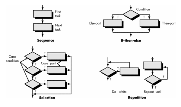
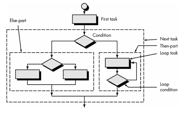
- Three control structures are required:
- sequence
- condition (if-then-else)
- repetition (looping)
- Reduces program complexity by enhancing readability, testability, and maintainability
Design Notation
- Flowcharts (arrows for flow of control, diamonds for decisions, rectangles for processes)


- Box diagrams (also known as Nassi-Scheidnerman charts - process boxes subdivided to show conditional and repetitive steps)
- Characteristics:
(1) functional domain (that is,
the scope of repetition or if-then-else) is well defined and clearly visible as
a pictorial representation
(2) arbitrary transfer of control
is impossible
(3) the scope of local and/or
global data can be easily determined
(4) recursion is easy to
represent

- Decision table (subsets of system conditions and actions are associated with each other to define the rules for processing inputs and events)

Steps to develop a decision table:
- List all actions that can be associated with a specific procedure (or module).
- List all conditions (or decisions made) during execution of the procedure.
- Associate specific sets of conditions with specific actions, eliminating impossible combinations of conditions; alternatively, develop every possible permutation of conditions.
- Define rules by indicating what action(s) occurs for a set of conditions.
Example
If the customer account is
billed using a fixed rate method, a minimum monthly charge is assessed for
consumption of less than 100 KWH (kilowatt-hours). Otherwise, computer billing
applies a Schedule A rate structure. However, if the account is billed using a
variable rate method, a Schedule A rate structure will apply to consumption
below 100 KWH, with additional consumption billed according to Schedule B.

- Program Design Language (PDL - structured English or pseudocode used to describe processing details)
- Characteristics
- Fixed syntax with keywords providing for representation of all structured constructs, data declarations, and module definitions
- Free syntax of natural language for describing processing features
- Data declaration facilities for simple and complex data structures
- Subprogram definition and invocation facilities

Design Notation Assessment Criteria
- Modularity (notation supports development of modular software)
- Overall simplicity (easy to learn, easy to use, easy to write)
- Ease of editing (easy to modify design representation when changes are necessary)
- Machine readability (notation can be input directly into a computer-based development system)
- Maintainability (maintenance of the configuration usually involves maintenance of the procedural design representation)
- Structure enforcement (enforces the use of structured programming constructs)
- Automatic processing (allows the designer to verify the correctness and quality of the design)
- Data representation (ability to represent local and global data directly)
- Logic verification (automatic logic verification improves testing adequacy)
- "Code-to" ability (easily converted to program source code)