SE 765 -
Distributed Software Development
CS 610 -
Introduction to Parallel and Distributed Computing
|
|
Lecture 7 |
Communication
· Interprocess communication fundamental to all distributed systems.
· Communication in distributed systems is always based on low-level message passing as offered by the underlying network.
· Expressing communication through message passing is harder than using primitives based on shared memory
· Modern distributed systems often consist of thousands or even millions of processes scattered across a network with unreliable communication.
· Unless the primitive communication facilities of computer networks are replaced by something else, development of large-scale distributed applications is extremely difficult.
Fundamentals
Layered Protocols
·
Due to the absence of shared memory,
all communication in distributed systems is based on sending and receiving (low
level) messages.
·
When process A wants to communicate
with process B, it first builds a message in its own address space.
·
Then it executes a system call that
causes the operating system to send the message over the network to B.
International Standards Organization (ISO) reference model: Open Systems Interconnection (OSI) Reference Model (Day and Zimmerman, 1983).
·
Protocols that were developed as part
of the OSI model were never widely used.
·
Underlying model useful for
understanding computer networks.
·
OSI model is designed to allow open systems to communicate.
·
An open
system is one that is prepared to communicate with any other open system
by using standard rules that govern the format, contents, and meaning of the
messages sent and received.
·
Rules are formalized into protocols.
·
Groups of computers communicate over a
network by agreeing on the protocols to be
used.
Two general types of protocols:
1.
Connection oriented protocols
o
Before exchanging data the sender and
receiver first explicitly establish a connection, and possibly negotiate the
protocol to use.
o
When done coomunicating,
the connection is terminated.
o
e.g.
telephone is a connection-oriented
communication system.
2.
Connectionless protocols
o
No advance setup.
o
The sender transmits the first message
when it is ready.
o
e.g.
Dropping a letter in a mailbox is an example of connectionless communication.
The OSI model
–
·
Communication is divided up into seven levels or layers.
·
Each layer deals with one specific
aspect of the communication.
·
Each layer provides an interface to
the one above it.
·
The interface consists of a set of
operations that together define the service the layer is prepared to offer its
users.
OSI Model |
||||
|
|
Data
unit |
Layer |
|
Function |
|
Host
Layers |
Data
|
Application
|
7 |
Network process to application |
|
Presentation |
6 |
Data representation and encryption |
||
|
Session |
5 |
Interhost
communication |
||
|
Segments |
Transport |
4 |
End-to-end connections and reliability |
|
|
Media
Layers |
Packets |
Network |
3 |
Path determination and logical addressing
(IP) |
|
Frames |
Data link |
2 |
Physical addressing (MAC & LLC) |
|
|
Bits |
Physical |
1 |
Media, signal and binary transmission |
|
Layer 7: Application Layer
·
Provides means for the user to access
information on the network through an application.
·
This layer is the main interface for
the user(s) to interact with the application and therefore the network.
·
Some
examples of application layer protocols include Telnet, applications which use
File Transfer Protocol (FTP), applications which use Simple Mail Transfer
Protocol (SMTP) and applications which use Hypertext Transfer Protocol (HTTP).
Layer 6: Presentation Layer
·
Transforms data to provide a standard
interface for the Application layer.
· MIME encoding, data compression, data encryption and similar manipulation of the presentation is done at this layer to present the data as a service or protocol developer sees fit.
·
Examples: converting an EBCDIC-coded
text file to an ASCII-coded file, or serializing objects and other data
structures into and out of, e.g., XML.
Layer 5: Session Layer
·
Controls the dialogues (sessions)
between computers.
·
It establishes, manages, and
terminates the connections between the local and remote application.
·
It provides for either duplex or
half-duplex operation and establishes checkpointing,
adjournment, termination, and restart procedures.
·
The OSI model made this layer
responsible for "graceful close" of sessions, which is a property of
TCP, and also for session checkpointing and recovery,
which is not usually used in the Internet protocols suite.
Layer 4: Transport Layer
·
Provides transparent transfer of data
between end users, thus relieving the upper layers from any concern while
providing reliable data transfer.
·
Controls the reliability of a given
link through flow control, segmentation/desegmentation,
and error control.
·
Some protocols are state and
connection oriented.
o This
means that the transport layer can keep track of the packets and retransmit
those that fail.
·
Best known example of a layer 4 protocol is the Transmission Control Protocol (TCP).
o The
transport layer is the layer that converts messages into TCP segments or User
Datagram Protocol (UDP), Stream Control Transmission Protocol (SCTP), etc.
packets.
Layer 3: Network Layer
·
Provides the functional and procedural
means of transferring variable length data sequences from a source to a
destination via one or more networks while maintaining the quality of service
requested by the Transport layer.
·
The Network layer performs network
routing functions.
·
Routers operate at this layer—sending
data throughout the extended network and making the Internet possible (also
existing at layer 3 (or IP) are switches).
o This
is a logical addressing scheme – values are chosen by the network engineer.
o The
addressing scheme is hierarchical.
·
The best known example of a layer 3
protocol is the Internet Protocol (IP).
Layer 2: Data Link Layer
·
Provides the functional and procedural
means to transfer data between network entities and to detect and possibly
correct errors that may occur in the Physical layer.
·
Best known example of this is
Ethernet.
·
On IEEE 802 local area networks, and
some non-IEEE 802 networks such as FDDI, this layer may be split into a Media
Access Control (MAC) layer and the IEEE 802.2 Logical Link Control (LLC) layer.
It arranges bits from physical layer into logical chunks of data, known as
frames.
·
This is the layer at which the bridges and switches operate.
·
Connectivity is provided only among locally attached network nodes
forming layer 2 domains for unicast or broadcast forwarding.
·
Other protocols may be imposed on the data frames to create tunnels and
logically separated layer 2 forwarding domains.
Layer 1: Physical Layer
·
Defines all the electrical and physical
specifications for devices.
o This
includes the layout of pins, voltages, and cable specifications. Hubs,
repeaters, network adapters and Host Bus Adapters (HBAs used in Storage Area
Networks) are physical-layer devices.
·
The major functions and services
performed by the physical layer are:
o Establishment
and termination of a connection to a communications medium.
o Participation
in the process whereby the communication resources are effectively shared among
multiple users.
o Modulation or
conversion between the representation of digital data in user equipment and the
corresponding signals transmitted over a communications channel.
·
Parallel SCSI buses operate in this
layer.
·
Various physical-layer Ethernet
standards are also in this layer;
o Ethernet
incorporates both this layer and the data-link layer.
·
The same applies to other local-area
networks, such as Token ring, FDDI, and IEEE 802.11, as well as personal area
networks such as Bluetooth and IEEE 802.15.4.
Sending a Message
When process A on
machine 1 wants to communicate with process B on machine 2:
1.
it
builds a message and passes the message to the application layer on its
machine.
·
This layer might be a library
procedure, for example, but it could also be implemented in some other way
(e.g., inside the operating system, on an external network processor, etc.).
2.
The application layer software then
adds a header to the front of the message and passes the resulting message
across the layer 6/7 interface to the presentation layer.
3.
The presentation layer adds its own
header and passes the result down to the session layer, and so on.
·
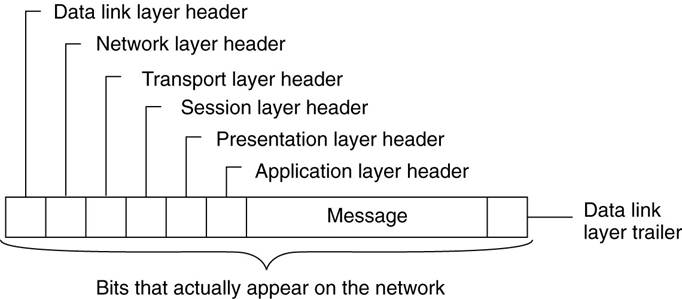
Some layers add not only a header to
the front, but also a trailer to the end.
4.
When it hits the bottom, the physical
layer transmits the message) by putting it onto the physical transmission
medium.
·
A typical message as it appears on the
network.
5.
When the message arrives at machine 2,
it is passed upward, with each layer stripping off and examining its own
header.
6.
Finally, the message arrives at the receiver, process B, which may reply to it using the reverse
path.
·
The information in the layer n header
is used for the layer n protocol.
Middleware
Protocols
·
Middleware is an application that
logically lives (mostly) in the application layer, but contains many
general-purpose protocols that warrant their own layers, independent of other,
more specific applications.
·
Middleware communication protocols
support high-level communication services.
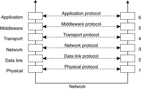
·
Adapted reference model for
communication
·
Compared to the OSI model, the session
and presentation layer have been replaced by a single middleware layer that
contains application-independent protocols.
Types of Communication
View middleware as an additional service in
client-server computing,
·
Viewing middleware as an intermediate
(distributed) service in application-level communication.
Example: An
electronic mail system.
·
The core of the mail delivery system
viewed as a middleware communication service.
·
Each host runs a user agent allowing
users to compose, send, and receive e-mail.
·
A sending user agent passes such mail
to the mail delivery system, expecting it, to deliver the mail to the intended
recipient.
·
The user agent at the receiver's side
connects to the mail delivery system to see whether any mail has arrived.
o
If so, the messages are transferred to
the user agent so that they can be displayed and read by the user.
Persistent Communication
An electronic mail system is a typical
example of communication persistent communication.
·
With persistent communication, a
message that has been submitted for transmission is stored by the communication
middleware as long as it takes to deliver it to the receiver.
·
The middleware will store the message
at one or several of the storage facilities (above figure).
o
Not necessary for the sending
application to continue execution after submitting the message.
o
The receiving application need not be
executing when the message is submitted.
Transient Communication
A message is stored by the communication
system only as long as the sending and receiving application are executing.
·
The middleware cannot deliver a
message if there is a transmission interrupt or the recipient is currently not
active -it will discard the message.
·
All transport-level communication services
offer only transient communication.
o
The communication system consists of
traditional store-and-forward routers.
o
If a router cannot deliver a message
to the next one or the destination host, it will drop the message.
Asynchronous Communication
A sender continues executing immediately after it has submitted its message for transmission.
· This means that the message is (temporarily) stored by the middleware immediately upon submission.
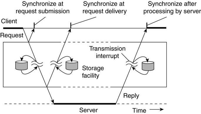
Synchronous Communication
A sender is blocked until its request is
known to be accepted.
·
Three points where synchronization can
take place:
1.
The sender may be blocked until the
middleware notifies that it will take over transmission of the request.
2.
The sender may synchronize until its
request has been delivered to the intended recipient.
3.
Synchronization may take place by
letting the sender wait until its request has been fully processed, that is, up
the time that the recipient returns a response.
Distributed Communications Classifications
a) Persistent asynchronous
communication.
b) Persistent synchronous
communication.
c) Transient asynchronous
communication.
d) Receipt-based transient
synchronous communication.
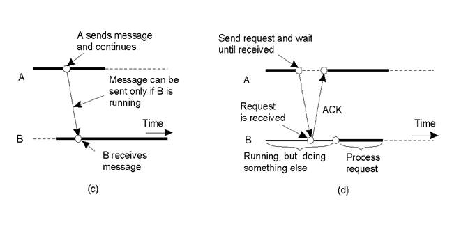
e) Delivery-based transient
synchronous communication at message delivery.
f) Response-based transient
synchronous communication.
Remote Procedure Call
Issue:
·
Many distributed systems have been
based on explicit message exchange between processes.
·
These procedures do not conceal
communication mitigating access transparency in distributed systems.
Solution:
·
Birrell
and Nelson (Birrell and Nelson 1984) suggested
allowing programs to call procedures located on other machines.
·
When a process on machine A calls a
procedure on machine B, the calling process on A is suspended, and execution of
the called procedure takes place on B.
·
Information can be transported from
the caller to the callee in the parameters and be
returned in the procedure result.
·
No message passing is visible to the
programmer.
·
This method is known as Remote
Procedure Call, or often just RPC.
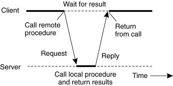
Basic RPC Operation
Conventional Procedure Call
·
Consider a call in C like
count = read(fd,
buf, nbytes);
where
fd
is an integer indicating a file
buf is an array of characters into which data are
read
nbytes
is another integer telling how many bytes to read
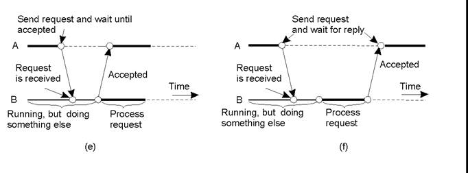
·
If the call is made from the main
program, the stack will be as shown in Figure(a)
before the call.
·
To make the call, the caller pushes
the parameters onto the stack in order, last one first, as shown in Figure (b).
·
After the read procedure has finished running,
it puts the return value in a register, removes the return address, and
transfers control back to the caller.
·
The caller then removes the parameters
from the stack, returning the stack to the original state it had before the
call.
(a) Parameter passing in a local procedure
call: the stack before the call to read.
(b) The stack while the called procedure is
active.
Note:
·
In C, parameters can be call-by-value or call-by-reference.
·
A value parameter, such as fd or nbytes, is simply copied to
the stack as shown in Figure(b).
·
To the called procedure, a value
parameter is just an initialized local variable.
·
The called procedure may modify it,
but such changes do not affect the original value at the calling side.
·
A reference parameter in C is a
pointer to a variable (i.e., the address of the variable), rather than the
value of the variable.
·
In the call to read( ), the second parameter
is a reference parameter because arrays are always passed by reference in C.
·
What is actually pushed onto the stack
is the address of the character array.
·
If the called procedure uses this
parameter to store something into the character array, it does modify the array
in the calling procedure.
·
The difference between call-by-value
and call-by-reference is quite important for RPC.
Client and Server
Stubs
·
RPC makes a remote procedure call look
as much as possible like a local call.
·
When read( )
is a remote procedure (e.g., one that will run on the
file server's machine), a different version of read, called a client stub, is put into the library.
·
Like the original read( ):
·
it
is called using the calling sequence.
·
it
makes a call to the local operating system.
· Unlike the original one read( ), it does not ask the operating system to provide data - it packs the parameters into a message and requests that message to be sent to the server as illustrated below.
· Following the call to send, the client stub calls receive, blocking itself until the reply comes back.
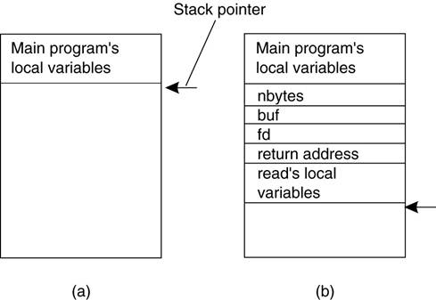
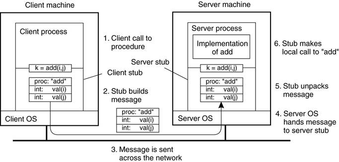
Principle of RPC between a client and
server program.
·
When the message arrives at the
server, the server's operating system passes it up to a server stub.
§ A
server stub is the server-side equivalent of a
client stub: it is a piece of code that transforms requests coming in over the
network into local procedure calls.
§ The
server stub will have called receive and be blocked waiting for incoming
messages.
§ The
server stub unpacks the parameters from the message and then calls the server
procedure in the usual way (figure above).
§ From
the server's point of view, it is as though it is being called directly by the
client—the parameters and return address are all on the stack where they
belong.
§ The
server performs its work and then returns the result to the caller in the usual
way.
·
When the server stub gets control back
after the call has completed, it packs the result (the buffer) in a message and
calls send to return it to the client.
·
After that, the server stub usually
does a call to receive again, to wait for the next incoming request.
·
When the message gets back to the
client machine, the client's operating system sees that it is addressed to the
client process (or actually the client stub, but the operating system cannot
see the difference).
·
The message is copied to the waiting
buffer and the client process is unblocked.
·
The client stub inspects the message,
unpacks the result, copies it to its caller, and returns in the usual way.
·
When the caller gets control following
the call to read( ),, all it knows is that its data are
available.
·
It has no idea that the work was done
remotely instead of by the local operating system.
·
Remote services are accessed by making
ordinary (i.e., local) procedure calls.
·
All the details of the message passing
are hidden away in the two library procedures, just as the details of actually
making system calls are hidden away in traditional libraries.
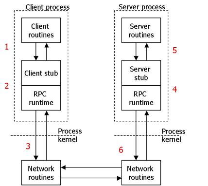
A remote procedure call occurs in the following steps:
1. The client procedure calls the client stub
in the normal way.
2. The client stub acts a proxy and builds a
message and calls the local operating system.
3. The client's OS sends the message to the
remote OS (via TCP/UDP).
4. The remote OS gives the message to the
server stub.
5. The server stub unpacks the parameters and
calls the server.
6. The server does the work and returns the
result to the stub.
7. The server stub packs it in a message and
calls its local OS.
8. The server's OS sends the message to the
client's OS.
9. The client's OS gives the message to the
client stub.
10. The client stub unpacks the result and
returns to the client.
Parameter Passing
Passing Value Parameters
Parameter
marshaling: There’s
more than just wrapping parameters into a message:
·
Packing parameters into a message is
called parameter marshaling.
·
Client
and server machines may have different data representations (think of
byte ordering)
·
Wrapping
a parameter means transforming a value into a sequence of bytes
·
Client
and server have to agree on the same encoding:
·
How are basic data values represented
(integers, floats, characters)
·
How are complex data values
represented (arrays, unions)
·
Client
and server need to properly interpret messages, transforming them into
machine-dependent representations.
The steps involved in a doing a remote
computation through RPC.
·
When the message arrives at the
server, the stub examines the message to see which procedure is needed and then
makes the appropriate call.
·
The actual call from the stub to the
server looks like the original client call, except that the parameters are
variables initialized from the incoming message.
·
When the server has finished, the
server stub gains control again.
·
It takes the result sent back by the
server and packs it into a message.
·
This message is sent back to the
client stub, which unpacks it to extract the result and returns the value to
the waiting client procedure.
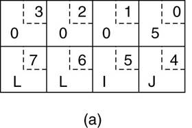
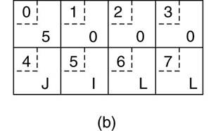
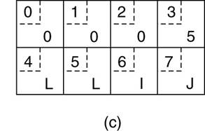
XDR (External data
representation)
Some machines, such as the Intel Pentium,
number their bytes from right to left, whereas others, such as the Sun SPARC,
number them the other way.
§ The
Intel format is called little endian and the
SPARC format is called big endian, after the
politicians in Gulliver's Travels who went to war over which end of an egg to break .
·
e.g., a procedure with two
parameters: an
integer and a four-character string.
o
Each parameter requires one 32-bit
word.
(a) The original
message on the Pentium.
(b) The message
after receipt on the SPARC.
(c) The message
after being inverted.
The little numbers
in boxes indicate the address of each byte.
Passing Reference
Parameters
How are pointers, or in general,
references passed?
·
Only with the greatest of difficulty,
if at all.
·
A pointer is meaningful only within
the address space of the process in which it is being used.
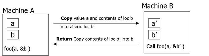
Solution: copy/restore
·
Copy the array into the message and
send it to the server.
·
The server stub can then call the
server with a pointer to this array, even though this pointer has a different
address than the second parameter of read.
·
Changes the server makes using the
pointer (e.g., storing data into it) directly affect the message buffer inside
the server stub.
·
When the server finishes, the original
message can be sent back to the client stub, which then copies it back to the
client.
·
In effect, call-by-reference has been
replaced by copy/restore.
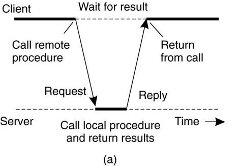
Conventional (Synchronous) RPC
- the client will block until a reply is returned.
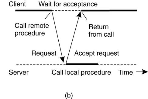
Asynchronous RPC -
client continues after issuing the RPC request.
·
The server immediately sends a reply
back to the client the moment the RPC request is received, after which it calls
the requested procedure.
·
The reply acts as an acknowledgment to
the client that the server is going to process the RPC.
·
The client will continue without
further blocking as soon as it has received the server's acknowledgment.
(a) Client -server interaction in traditional
RPC. (b) The interaction
using asynchronous RPC.
Example: DCE RPC
·
Distributed Computing Environment
(DCE) - developed by the Open Software Foundation (OSF)
·
Representative of RPC systems
·
Specifications adopted in Microsoft's
base system for distributed computing, DCOM.
·
DCE is a true middleware system in
that it is designed to execute as a layer of abstraction between existing
(network) operating systems and distributed applications.
·
Take a collection of existing
machines, add the DCE software, and then run distributed applications, all
without disturbing existing (nondistributed)
applications.
·
Client-server model is DCE programming
model
·
All communication between clients and
servers takes place by means of RPCs.
DCE Services:
Distributed file service
- worldwide file system that provides a transparent way of accessing any file
in the system in the same way.
Directory service
- keeps track of the location of all resources in the system (e.g. machines,
printers, servers, data, etc.)
Security service
- provides access restrictions.
Distributed time service
- attempts to keep clocks on the different machines globally synchronized.
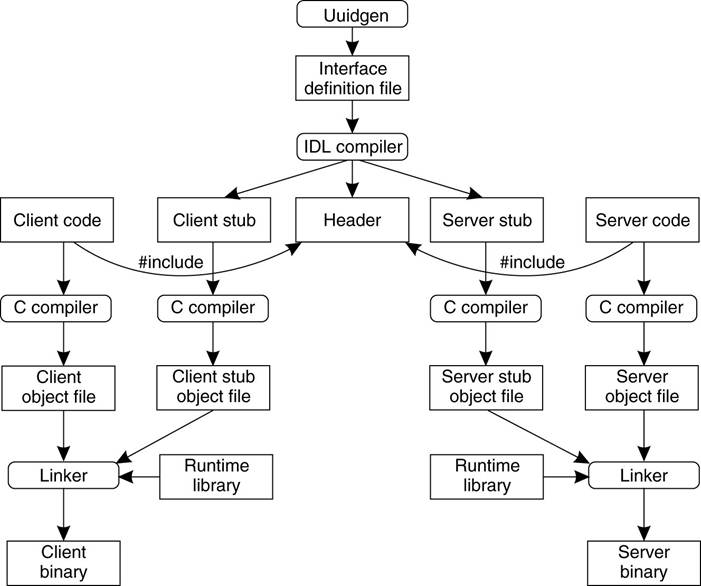
Writing a Client
and a Server
·
The steps in writing a client and a
server in DCE RPC.
Interface Definition Language
(IDL)
·
An Interface
Definition Language (IDL) is a language that is used to define the interface
between a client and server process in a distributed system.
·
Each interface definition language has
a set of associated IDL compilers, one per supported target language.
·
An IDL compiler compiles the interface
specifications, listed in an IDL input file, into source code (e.g., C/C++,
Java) that implements the low-level communication details required to support
the defined interfaces.
§ The
output of the IDL compiler consists of three files:
1.
A header file (e.g., interface.h, in C terms).
2.
The client stub.
3.
The server stub.
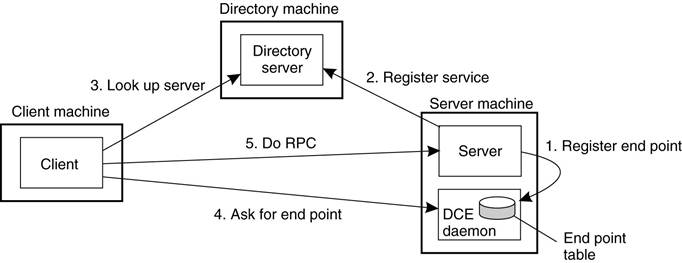
Binding a Client
to a Server
Client-to-server binding in DCE.
Message-Oriented Communication
Message-Oriented Transient Communication
·
Message-oriented model using transport
layer - transport-level sockets
Socket
- communication end point to which an application can write data that are to be
sent out over the underlying network, and from which incoming data can be read.
·
Developed in the early 1980s at the
· Its implementation is usually requires kernel code.
· It is the de facto standard for communications programming.
· Used for point-to-point communications between computers through an inter-systems pipe. Namely can use the UNIX read, write, close, select, etc. system calls.
· There are higher level tools for programs that span more than one machine. (e.g. RPC, DCOM ).
· Supports broadcast.
· Available on every UNIX system that I know of and somewhat available in WIN32.
· Built for client/server development.
· Supports two types of communications that sit on top of the TCP Internet datagrams.
§ TCP
- connection oriented, stream, reliable.
§ UDP - connectionless, record oriented, unreliable.
The socket primitives for TCP/IP.
|
Primitive |
Meaning |
|
Socket |
Create a new communication end point |
|
Bind |
Attach a local address to a socket |
|
Listen |
Announce willingness to accept connections |
|
Accept |
Block caller until a connection request
arrives |
|
Connect |
Actively attempt to establish a connection |
|
Send |
Send some data over the connection |
|
Receive |
Receive some data over the connection |
|
Close |
Release the connection |
|
Write |
Send data on the connection
|
|
Read |
Get data that was sent on the
connection
|
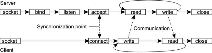
Servers execute
the first four primitives - in the order given.
Connection-oriented communication pattern
using sockets.
The Message-Passing Interface
(MPI)
· The Message Passing Interface (MPI) is a library specification for message passing.
·
It is a standard API that can be used
to create applications for high-performance multicomputers.
·
Specific network protocols
(not TCP/IP)
·
Message-based
communication
·
Primitives for all 4 forms
of transient communication (+ variations)
·
Over 100 functions
·
Vendors + Open Source
-- IBM, Intel, TMC, Meiko, Cray, Convex, Ncube, OpenMPI
Some of the message-passing primitives of
MPI.
|
Primitive |
Meaning |
|
MPI_bsend |
Append outgoing message to a local send
buffer |
|
MPI_send |
Send a message and wait until copied to
local or remote buffer |
|
MPI_ssend |
Send a message and wait until receipt
starts |
|
MPI_sendrecv |
Send a message and wait for reply |
|
MPI_isend |
Pass reference to outgoing message, and
continue |
|
MPI_issend |
Pass reference to outgoing message, and
wait until receipt starts |
|
MPI_recv |
Receive a message; block if there is none |
|
MPI_irecv |
Check if there is an incoming message, but
do not block |
Further
Message-Oriented
Persistent Communication
• Known as: “Message-queuing
systems” or “Message-Oriented Middleware (MOM)”.
• They support persistent,
asynchronous communications.
• Typically, transport can take
minutes (hours?) as opposed to seconds/milliseconds.
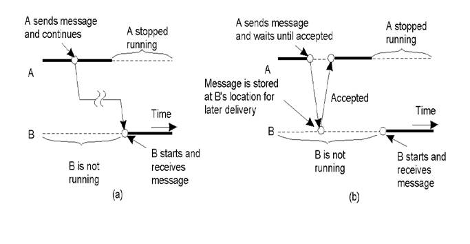
• The basic idea: applications communicate by putting messages into and taking
messages out of “message queues”.
• Only guarantee: your message will
eventually make it into the receiver’s message queue.
• This leads to “loosely-coupled”
communications.
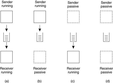
Four combinations for loosely-coupled communications using queues.
Basic interface to a queue in a
message-queuing system.
|
Primitive |
Meaning |
|
Put |
Append a message to a specified queue |
|
Get |
Block until the specified queue is
nonempty, and remove the first message |
|
Poll |
Check a specified queue for messages, and
remove the first. Never block |
|
Notify |
Install a handler to be called when a
message is put into the specified queue |
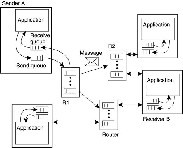
General Architecture of a
Message-Queuing System
Message-Queuing System Architecture
·
Messages are “put into” a source
queue.
·
They are then “taken from”
a destination queue.
·
Queues are managed by queue
managers
§ They move a message from a source queue to a destination queue.
§ Special
queue managers operate as routers or relays: they forward incoming messages to
other queue managers.
·
The general organization of a
message-queuing system with routers.
The Role of Message Brokers
· Often, there’s a need to integrate new/existing apps into a “single, coherent Distributed Information System (DIS)”.
·
Problem: different message formats exist in legacy systems (cooperation
and adherence to open standards was not how things were done in the past).
§ It may not be convenient to “force” legacy systems to adhere to a
single, global message format (cost!?).
§ It is often necessary to live with diversity (there’s no choice).
·
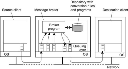
Solution: the “Message Broker”.
Message Brokers (aka “Interface engine”)
·
In message-queuing systems,
conversions are handled by special nodes in a queuing network, known as message
brokers.
·
A message broker acts as an
application-level gateway in a message-queuing system.
·
Purpose - convert incoming messages so
that they can be understood by the destination application.
§ Note:
a message broker is just another application - not considered to be an integral
part of the queuing system.
o
Message brokers can be simple (
reformat messages) or complex (find associated applications, convert data)
·
The general organization of a message
broker in a message-queuing system.
Message-Queuing (MQ) Applications
·
General-purpose MQ systems
support a wide range of applications, including:
– Electronic mail.
– Workflow.
– Groupware.
– Batch Processing.
·
Most important MQ
application area:
– Integration of a widely dispersed collection of database
applications (which is all but impossible to do with traditional RPC/RMI
techniques).
–