CS835
- Data and Document Representation & Processing
|
|
Lecture 12 - Hypermedia VI – Physical
Hypermedia |
Augmented Reality (AR)
- Virtual reality is a computer generated, interactive, three-dimensional environment in which a person is immersed.
- Augmented Reality is a variation of Virtual Reality in which the user sees the real world, with virtual objects superimposed upon or composited within the real world.
- AR supplements reality, rather than completely replacing it.
- Ideally, it should appear to the user that the virtual and real objects coexisted in the same space
- AR possesses three desired characteristics:
1) Combines real and virtual
2) Interactive in real time
3) Registered in 3D

Real desk with virtual lamp and two virtual chairs
HOW TO AUGMENT REALITY
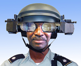
Augment the user
The user wears or carries a device, usually on the head or hands, to obtain information about physical objects.
Augment the physical object
· The physical object is changed by embedding input, output or computational devices on or within it.
e.g. Electronic bricks contain simple electronic
devices such as sensors (light, sound, touch, proximity), logic devices
(and-gates, flip-flops, timers) and action bricks (motors, lights).
·
Ubiquitous computing in which specially-created objects are detected by
sensors placed throughout the building.
Augment the environment
surrounding the user and the object
· Independent devices provide and collect information from the surrounding environment, displaying information onto objects and capturing information about the user's interactions with them.
e.g.
o
The Digital Desk uses a video camera to detect where a user is
pointing and a close-up camera to capture images of numbers, which are then
interpreted via optical character recognition.
o
A projector overhead projects changes made by the user back onto the
surface of the desk.
1) The user may have a column of numbers printed on a particular page.
2)
The user points to numbers, the digital desk reads and interprets them,
and then places them into an electronic spreadsheet, which is projected back
onto the desk.
3)
Using his fingers, the user can modify the numbers and perform
"whatif" calculations on the original data
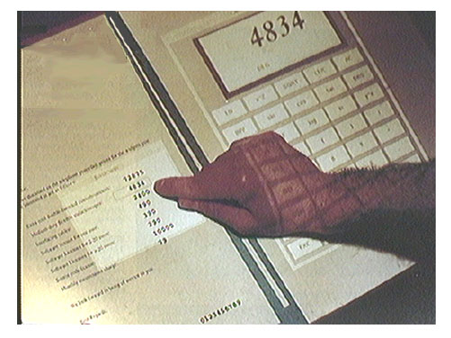
A user points to a column of numbers printed on a paper
document and then uses an electronic calculator projected on the desktop.
·
eTag system - simple connection between physical object and an action
or a piece of information on the Web, such as the related Amazon page.
·
FindEntity system [ http://www.thax.de/english/frame.html
] - provides support for locating physical material inside buildings and
offices using Radio Frequency Identification (RFID).
Examples of augmented reality approaches, with relevant
technologies and applications
AR Applications
- Medical Visualization
- Enhanced Reality Visualization
Peel back the MRI skin and see where the internal structures are located relative to the viewpoint of the camera


Superposition of MRI Scans on patients
- Manufacturering and Repair
- KARMA
(Knowledge-based Augmented Reality
for Maintenance Assistance)
Prototype system that uses a see-through head-mounted display to explain simple end-user maintenance for a laser printer


Left Figure: Attached several Logitech 3D trackers (the small triangles in
the figure shown
above) to key components of the printer, allowing the system to monitor
their position and orientation
Right
Figure: shows a virtual world designed by KARMA, viewed ``live'' through a
see-through head-mounted display.
- Boeing (Davis Mizell)
- AR technology to guide a technician in building a wiring harness that forms part of an airplane's electrical system.
- Currently, technicians use large physical layout boards to construct such harnesses, and Boeing requires several warehouses to store all these boards.

- System guides a mechanic who, although skilled, may not have experience with a given piece of equipment.
- By using AR, the mechanic is guded step-by-step through a disassembly procedure, thus reducing errors and risks while increasing productivity and knowledge to the mechanic.
- This optical see-through AR system uses simple line drawings and text overlayed ontothe physical world.
- The system consists of a Polhemus fastrack electromagnetic tracker and Virtual Vision VCAP - 10000 HMD. The application was written in C++ as a standard Windows 32 application and has been ported to Linux.
- Features of Augmented Reality System:
1. Direct placement of information
2. Can be tuned to intended job training
3. Technology can be applicable to any sequenced procedure
4. Applications include assembly, disassembly, maintenance and training
5. Utilizes either optical see-through or video see-through
6. Can reduce or potentially eliminate paper training material
- Annotation and Visualization
Used to annotate objects and environments with public or private information.
- European ComputerIndustry Research Centre (ECRC), a user can point at parts of an engine model and the AR system displays the name of the part that is being pointed to.

The user points at the exhaust manifold on an engine model, and the label "exhaust manifold" appears.
- Columbia University - Steve Feiner
Windows on
the World - 2D Windows for 3D Augmented Reality
Windows attached from a standard user interface
onto specific locations in the world

- Figure shows a virtual world populated by three X windows, photographed ``live'' through a see-through head-mounted display.
- Window at the right is an xload load-average meter that is fixed to the corner of a portable workstation.
- The xpostit window at the upper left is attached to the 3D tracker ``bolo tie'' so it moves when the user moves.
- The window at the bottom is the control panel for a hypermedia system. It is fixed to the head-mounted display, so it always occupies the same location relative to the user's head.
- Office of the Future
- Use real-time computer vision techniques to dynamically extract per-pixel depth and reflectance information for the visible surfaces in the office including walls, furniture, objects, and people, and then to either project images on the surfaces, render images of the surfaces, or interpret changes in the surfaces.
- Designate every-day (potentially irregular) real surfaces in the office to be used as spatially immersive display surfaces
- Project high-resolution graphics and text onto those surfaces.
- Transmit dynamic image-based models over a network for display at a remote site.
- Interpret dynamic changes in the surfaces for the purposes of tracking, interaction, or augmented reality applications.

To accomplish the simultaneous capture and
display:
- Ceiling lights are replaced by computer controlled cameras
- "Smart" projectors are used to capture dynamic image-based models with imperceptible structured light techniques
- Display high-resolution images on designated display surfaces.
- By doing both simultaneously on the designated display surfaces, one can dynamically adjust or autocalibrate for geometric, intensity, and resolution variations resulting from irregular or changing display surfaces, or overlapped projector images.
- National Tele-Immersion Initiative
- Enable users at geographically distributed sites to collaborate in real time in a shared, simulated environment as if they were in the same physical room.
- 3D real time acquisition data ("real" data),
- 3D synthetic objects ("virtual" data) and user interactions with 3D objects using virtual laser pointer.
- The participants in the session are not only able to see each other in 3D but they were able to engage in collaborative work.

Telecubicle - 3D real time acquisition data combined with static 3D
background (latter is a laser scan of an office). Remote participant Amela
Sadagic in Armonk, NY, and a local participant Wei-Chao Chen in Chapel Hill,
NC.

- Camera rig used for real-time 3D acquisition.
- Seven digital cameras arranged in semicircle.
- Each triple of neighboring cameras produces independent set of 3D data ("view"), so there are 5 "views" in total.
- The final 3D model is made by combining 5 views into one.
- MARS (Mobile Augmented Reality Systems)
- Aimed at exploring the synergy of two fields of user interface research:
- Augmented reality (AR), in which 3D displays are used to overlay a synthesized world on top of the real world,
- Mobile computing, in which small and inexpensive computing devices and wireless networking allow users to have access to computing facilities while roaming the real world.
- Reserarch focus :
- Identifying generic tasks a mobile user would want to carry out on a context aware computing system
- Defining a comprehensive set of re-usable user interface components for mobile augmented reality applications.
- Making combined use of different display technologies ranging from head-worn to hand-held to palm-top to best support a mobile user.

Prototype campus information system.
The user wears a backpack and headworn display, and holds a handheld display
and its stylus

- View shot through the see-through headworn display, showing campus buildings with overlaid names.
- Labels increase in brightness as they near the center of the display.
- Philosophy Building with the "Departments" menu item highlighted.
- After the "Departments" menu item is selected, the department list for the Philosophy Building is added to the world, arrayed about the building.
- Selecting the "Departments" menu item causes an automatically-generated URL to be sent to the web browser on the handheld computer, containing the department list for the Philosophy Building.
- Actual home page for the English and Comparative Literature department, as selected from either the generated browser page or the department list in the augmented world.


Implementation Framework
- Hardware
- Backpack computer (with 3D graphics acceleration)
- Differential GPS system
- Head-worn display interface (with orientation tracker)
- Spread spectrum radio communication link
- The user also holds a small stylus-operated computer that can talk to the backpack computer via the spread spectrum radio channel.
- Use only off-the-shelf hardware
- Settled for items that were far bulkier than we would like them to be
e.g. a FieldWorks laptop machine for the backpack computer, which offers
us three PCI and three EISA expansion slots (currently used among others for a
powerful 3D graphics adapter and a 6-serial port expansion card).
- Software
- Coterie prototyping environment that provides language-level support for distributed virtual environments.
- On the above hardware configuration the main mobile AR application running on the backpack computer receives continuous input from:
- the GPS system
- the orientation head tracker,
- the trackpad (mounted on the back of the handheld computer).
- It generates and displays at an interactive frame rate the overlaid 3D graphics and user interface components on the headworn display.

|
|
Physical Hypermedia
Physical
Hypermedia: Organizing Collections of Mixed Physical and Digital Material,
Kaj Grønbæk, Jannie F. Kristensen, Peter Ørbæk Mette Agger Eriksen
Physical Hypermedia – make objects from physical world into first class
objects in hypermedia systems.
Ubiquitous and pervasive
computing
·
Main
focus to develop infrastructures for dealing with display enabled devices in a
variety of different scales, from interactive walls to PDAs, cell phones, and
wrist watches etc.
·
Far
less focus on how to associate computing with familiar physical artifacts such
as paper, folders, binders, models, samples etc. as being used in many work
domains
Augmented Reality
- Focus is on superimposing, tagging and tracking
single objects, and development of new materials such as augmented paper
(e.g. eInk and Anoto).
Hypermedia and spatial
relationships
- Spatial hypermedia (Aquanet and VIKI ) can be
thought of as using a large2D space (a canvas) for sorting information or
organizing brainstorm notes for writing.
- Spatial hypermedia supports this kind of
organization by allowing items or "cards" to be generated and
placed on a "table" (space).
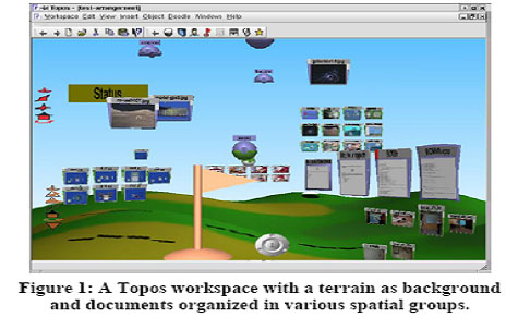
- Topos is the infrastructure used for the
following system.
- Topos supports 3D organization of models and
documents
- It can be used to support both abstract spatial hypermedia
with open unfurnished spaces and concrete spatial hypermedia using a
building or landscape as a “background” for relative placement of
material.
- The central concept in Topos is the workspace.
Challenge of bridging between physical and
digital material
- Physical material such as paper, clips, often
relate to digital material in terms of directories and documents of
different types
- Very little support for maintaining this
relationship.
- Approach: integrate RFID tagging system with
Topos to support for creating, manipulating, and maintaining this
relationship in an interactive environment.
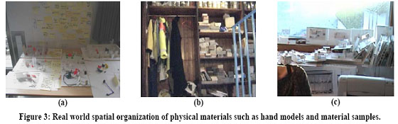
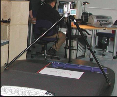
Empirical studies:
- The organization and management of material in a
specific work setting of landscape architects.
- The studies show:
1) Landscape architects take different approaches for
organizing material depending on the degree of formalization of procedures in
terms of work context.
2) Physical space is not just used for organizing with
the purpose of re-finding material
3) It is also used as an exhibition of ongoing work, as
well as the creation of an inspirational and creative atmosphere.
- The main purposes of organizing physical objects
is documentation, inspiration, and management.
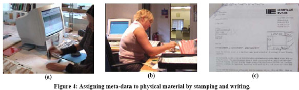
- The use of Meta-data and annotation is to be
able to re-find and recognize material for later use and to place it in
relevant contexts.
- For the researchers and office workers the
relevant material is typically paper (usually letter size) and books
- For designers and architects, the range of forms
and materials is much broader including cardboard models, large drawings,
bricks, plants etc.
- Must Create a “Context” to to create an
environment for:
- organizing and managing mixtures of physical
and digital material
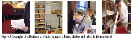
- describing, understanding, and analyzing collectional
artifacts in relation to the collectional actions performed
Abstractions of collectional actions
- The notions of space in the mixed physical and
digital environment
- The concept of a workspace is the main
structuring mechanism for organizing material in different types of
metaphorical or literal collections supported with free-form arrangement
or specific graphical arrangements such as rows and tables.
- This infrastructure in itself supports spatial
memory, as well as management of different kinds of digital material.
- In this way it supports a better conceptual
understanding of mapping the digital and the physical organization of
material and information
- It does not in itself provide direct links
between acts of organizing materials in the digital and physical
environments.
·
Relationships
between physical and digital world:
1.
Physical-only: Only physical object, the digital world has no trace of the
object, at all.
2.
Physical-with-digital-id: The digital world posses an ID plus some meta-data
relating to the physical object but no digital representation; for example: a
stone or a brick with an RFID tag on it.
3.
Physical-with-low-resolution-digital representation: a pen tracked drawing, a
scanned document or a photo of an object.
4.
Physical-generated-from-digital: a printed map, drawing or report.
5. Digital-only: Content that cannot be
printed or otherwise made physical/tangible, e.g. a video, sound or source
files (they may be stored on removable media like CD/DVD, but the content cannot
be accessed in the non-digital physical world).
- Working with physical hypermedia prototypes:
- Tagging – registering material and detecting
collectional actions
- Use of RFID to register physical material and
generate a digital ID in Topos.
- Associate a tag with a Topos object according
to the ID.
- If object tags have been removed, the linked
digital counterparts are marked by a red upper left corner.
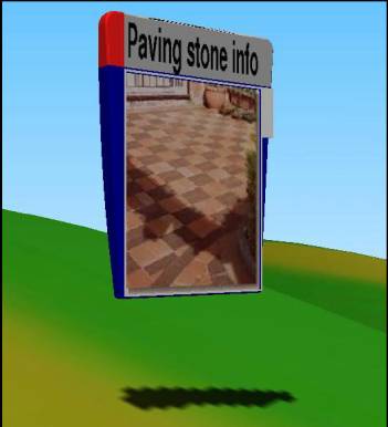
A document object in
Topos. A red corner (top left) indicates that a tagged item is linked to it but
not present at the tag-reader.
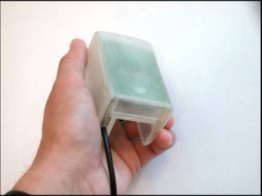
RFID reader: a hand-held
that only reads a single tag at a time.
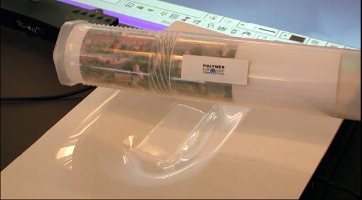
A
tube with an associated collection tag is placed on the tag-reader.
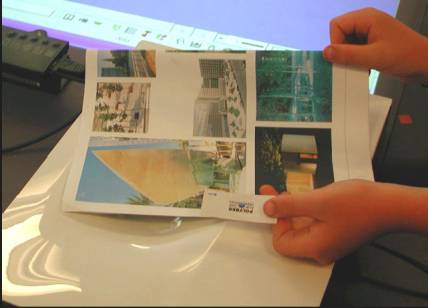
· Representing physical material – snapscanning
Design is a circular behavior
o
a snapshot of a sketch
in Topos makes the use of tags more efficient and flexible.
The first working prototype
of the “Snapscanner” allowing taking a snapshot and linking a tag to the
physical material in one operation.
TooLTags
· A tooltag is an RFID-tag
which is coupled to a command in the Topos hypermedia system rather than to a
piece of information.
· Allows issuing of commands
in Topos by placing the physical tooltag on the tag-reader alone or together
with a piece of physical material.
Tooltags: specific RFID tags
have been associated with commands to be invoked via the tag-reader.
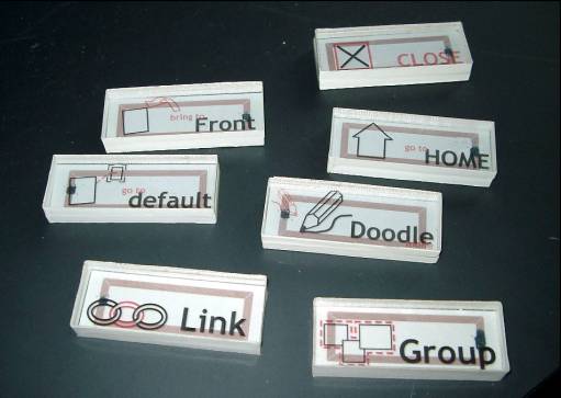
Invoking a command on an object by placing object and tooltag on the RFID reader.
Modeling Physical Hypermedia Applications,
Silvia
Gordillo Gustavo Rossi Fernando Lyardet
·
Example scenario –
o
Museum in which visitors are equipped with portable
computer devices, and there is some location sensing mechanism.
o
When the visitor stands in front of an artwork, he
can see its digital representation.
o
He is presented with a set of anchors that allows
him to navigate to other nodes (information items) related with the artwork.
o
When one of these nodes represents a physical
object, he is informed on how to reach that object (perhaps another artwork);
o
Can choose to traverse the physical space (“walk”
the link) towards this node or just continue his tour.
o
Not just augmenting the physical object (artwork)
with some digital information but also providing some kind of linking to other
digital or physical objects.
·
Approach to model PH applications extends the
Object-Oriented Hypermedia Design Method (OOHDM) by adding new abstractions and
re-defining the semantics of basic navigational behaviors.
The Design Approach
·
They define a PH application as a hypermedia
application (i.e. the access to information objects is done by navigation), in
which all or some of the objects of interest are real-world objects which are
visited by the user “physically”.
·
They assume that in a PH application there is some
underlying location-sensing technology that allows the application to be aware
of the actual user’s position.
·
Two different ways to implement hypermedia
navigation:
- the usual way
- selecting an anchor and accessing the target object
- physical way -
the user must change his position and walk towards the object
·
Must specify unambiguously the system’s intended
structure and behavioral semantics.
·
Must express which are the objects of interest and
their properties including:
o their
locations
o how
they are linked
o which
links should be implemented as conventional
o which
should be “walked” by the user
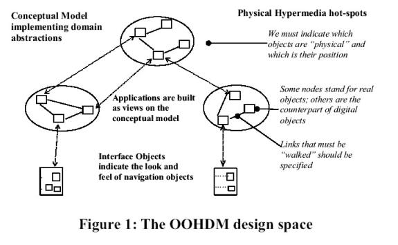
Basic Design Framework
·
OOHDM partitions the development space into four
activities:
o conceptual
modeling
o navigation
design
o abstract
interface design
o implementation
·
During conceptual modeling we describe the
application classes and their relationships using UML.
o Focus
is placed on generic application’s behavior
o application
is modeled neutrally with respect to navigation issues
·
In OOHDM, a hypermedia or Web application is seen as
a navigational view over the conceptual model
o can
specify different views according to the user profile or role.
o can
define a different navigational structure, which will reflect objects and
relationships in the conceptual schema according to the tasks this kind of user
must perform.
o The
navigational structure of a Web application is defined by a schema, containing
navigational classes such as nodes, links, anchors and access structures.
o The
semantics of nodes, links and anchors are as usual in hypermedia applications.
o Access
structures, such as indexes, represent possible ways for starting navigation.
·
The abstract interface model defines which interface
objects the user will perceive (in particular how nodes will look like) and
which interface transformations will take place.
·
During implementation the whole set of models
is mapped into a run-time environment.
·
OOHDM does not prescribe a particular strategy for
implementing a hypermedia or Web application
·
The design style facilitates the use of
object-oriented languages and architectural styles such as the
Model-View-Controller metaphor.
Dealing with physical Objects
·
OOHDM meta-model extended by adding the concept of
Physical Object.
·
A physical object is an application object that can
be explored “physically”
o it will
have a physical presence in the system
o we can
sense if the user is near it
o e.g.
the museum example we may be interested
in modeling artworks and even rooms as physical objects.
o Approach
for modeling physical objects:
§
consider that not all objects in a class (e.g.
Artwork) must be tagged as physical
§
e.g. relate artworks that exist physically with
others that are
·
not in exhibition
·
are in another geographical place
·
simply do not exist anymore.
§
Representing physical objects as sub-classes of a
particular class (Artwork) introduces a specialization criteria that might
collide with others in the intended domain (paintings, sculptures, etc)
o Chosen
to model physical objects as roles that can be assumed by conceptual objects.
§
A role type (in this case “physical”) indicates
those properties and behaviors of an object when playing that role.
§
Roles can easily be mapped to implementation settings
using for example decorators.
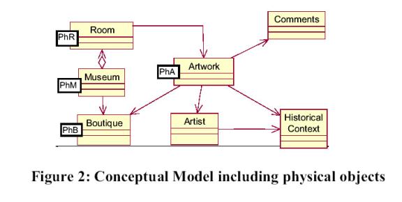
- Simple
conceptual model for the physical museum; roles are described using the
notation that extends UML with roles
- Artworks,
Rooms, Boutiques and the Museum itself are physical objects
There is a specific role type for each of them.
·
Physical objects are characterized by an attribute position whose semantics depends on the location
sensing technology
o Must be
refined for each application
o Different
role types (e.g. Museum and Boutique) might use different ways of location
sensing and representation
§
e.g. infrared position technology may require might be implemented using just an identifier,
§
outdoor applications that use GPS or other sensing
techniques, position must be implemented using more complex
location models.
·
Physical objects implement the inFrontOfMe (user) behavior that is triggered by the
underlying software when the user is sensed to be in the object’s vicinity.
o Standard
behavior is to open the corresponding node
o Also
implement the howToReachFrom (location) which
is used by walking links to indicate how the user can find the object.
·
Separating the conceptual from the physical aspect
of an object :
o allows
decoupling of design decisions
o allows
building of different browsing strategies according to the dimension considered
(e.g. physical or digital)
Specifying Navigation aspects
·
The navigation schema shows which nodes the user
will perceive and which links he can follow.
·
Nodes are built from conceptual objects and links
are derived from relationships in the conceptual model.
·
Cornerstones of OOHDM is that a different navigation
schema can be built for different user roles.
·
Museum application - can for example build a
different navigation schema for the regular visitor or for an expert (for
example a person working in the Museum).
o Some
artworks might be even (physically) inaccessible for a visitor, while the
museum worker should be able to access them for performing his work.
·
Differences between a conventional and a physical
hypermedia regarding the navigational schema:
o the
activation of nodes
o the
semantics of link traversal
·
Conventional hypermedia - a node is opened when we
navigate a link having that node as a target.
o Preserve
this behavior for “pure” digital nodes
o A node
that stands for a physical object should only be opened when the user is facing
the object
o introduced
changes in the physical objects (role) classes and in the link class behaviors.
·
Different navigation semantics - walking links
(WLinks) - those links whose target node is the digital counterpart of a
physical object.
·
Main difference between the operational semantics of
a navigational and a walking links:
o navigational
links close the current node and opens the target node
o walking
links indicate the user’s intention to reach the corresponding physical
object
·
the link invokes the howToReachFrom behavior in the physical object
corresponding to the target node, using as a parameter the current user
location.
·
Figure - the navigational schema for the visitor
user role that corresponds to the conceptual model.
·
WLinks with a <<W>> in the style of UML
stereotypes [10]; as said before we can have “non-walking” instances of a WLink
simply by specifying it at the instance level.
